Serial port

The serial port is a serial communication physics interface to transmit and receive information by 1 bit in once (unlike parallel port) [1]. In most of the history of the personal computer, the data were transmitted to a modem, a terminal, the device of other various peripheral devices through a serial port.
All the interfaces such as ethernet, FireWire and the USB send data as a serial stream, but terms "serial port" are usually identified with the hardware which RS-232 standard for the purpose of the connection with the communication device similar to modem and it and high rank compatibility or a low rank are compatible with.
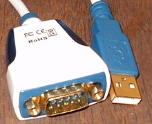
A converter between serial - USB is necessary to enable the compatibility with the RS-232 serial number device with the modern computer without a serial port. I still use a serial port in an industrial automation system, a scientific instrument, application such as the point-of-sale terminal system and for some industry and the consumer product. The server computer may use a serial port as a control console for the diagnoses. The network apparatus often uses a serial console for setting (such as a router and the switch). Because the serial port is simple and is cheap and a console function is standardized highly and spreads, I am still used in the field of the network apparatus. The serial port needs almost none of the software support from a host system.
Table of contents
Hardware
I converted a letter into an async serial number form and converted a letter into an async serial number form in the computer like IBM PC adversely, and it was more automatic, and there was the thing which used an integrated circuit called UART which took care of the structure in the timing of data. It was for the transmission of the data through the output pin and used a CPU by the very low-cost system in substitution for UART as having been seen in an early home computer by using a ビットバンギング technology. The minicomputer and the microcomputer before large scale integration (LSI) UART integrated circuits spread were equipped with the serial port which consisted of the plural small scale integrated circuits which implemented a shift register, logic gate, the counter for the serial port and all other logics.
The early home computer was the pin out that was incompatible with RS-232 and was often equipped with the serial port which was proprietary that was the battery level which was incompatible with RS-232. Such a serial port is not able to bear a generated battery level, and the mutual use with the RS-232 device may be impossible to lock a user to the product of the authorized supplier, and to enter it because there is various difference.
A more complicated serial communication standard was enabled at current high speed such as USB and FireWire to substitute by a low-priced processor in RS-232. By a low-priced processor, I come to be able to connect the device which less works by the serial connection that is low speed well such as mass storage, music and the video device.
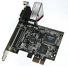
Even if I turn on a pin header and can access it, at least one serial port is still put on the motherboard of many personal computers. RS-232 connector port is omitted to save space with Small form factor system and the laptop, but the circuit still exists. Because RS-232 became the standard and was very long, the circuit necessary to control a serial port became very cheap. Furthermore, RS-232 often exists as the single tip which I sometimes matched with the circuit for the parallel port.
DTE and DCE
The individual signals of the serial port must connect the output of one device to the input of another device at time to unidirectionally connect two devices. The devices are classified in "DTE" (Data Terminal Equipment, DTE) and two kinds of "data circuit-terminating equipment" (Data Circuit-terminating Equipment, DCE). The line which is the output to DTE device is input to a DCE device, and the line which is the input to DTE device is the output to a DCE device. Therefore, I can connect a DCE device to DTE device with a straight cable broadcasting cable. As custom, a computer and the terminal are DTE, and a modem and a peripheral device are DCE.
When it is necessary to connect two DTE devices (but or it is very rare two DCE devices), you must use the crossover null modem by the form of either adapter or cable.
Connector

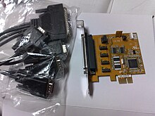
Originally 25 pin D type connectors were appointed in the RS-232 standard, but decided most of personal computer designers to implement only the subset of full standards. They sacrificed the compatibility with the standard in exchange for the use of the connector (DE-9 used in IBM PC-AT of the material in particular) which was cheap, and was more compact. Because I wanted to offer a serial interface card equipped with two ports, it was necessary for IBM to lower the size of the connector to fit single card back panel. If it is DE-9 connector, I fit a card equipped with the DB-25 connector which is another connector. This DB-25 connector was changed for a reason same as DE-9 connector by Centronics specifications of the material, too. The serial port was usually built in 9 pin connectors to save cost and space since IBM PC-AT was introduced. However, it is insufficient even if 9 pin D-subminiature connectors exist because 9 pin D-subminiature connectors were used for a video, joy-stick and other purposes to really make that connection depends on a serial port clear.

There is the thing equipped with the serial port using the faun connector in the electronic device downsized like a graph electronic calculator and a mobile amateur radio communications machine and a transmission and reception combined use radio apparatus, and the connector is in particular usually smaller than 2.5 or 3.5mm. Furthermore, in these electronic devices, there is the thing using 3 most basic line interfaces.
Most of models of Macintosh adopted the RS-422 standard that was a relative of RS-232 using Mini-DIN connector made in Germany except the earliest model willingly mainly. I put one set of two ports on Macintosh as a standard for the connection to a printer and a modem, but there was the thing which only a port of unified one was equipped with because space-saving in the PowerBook laptop.
I appoint 20 different signal connection in the standard. Because most devices use only the several signals, a smaller connector is often used. For example, 9 pin DE-9 connectors were used in a PC compatible with most IBM after the IBM PC AT and were standardized as TIA-574. A modular connector is used recently. 8P8C connector is the most common. I appoint pin allocation in the EIA/TIA 561 standard, but "Yost serial number device wiring standard" [2] that Dave Yost invented (and it spread in "Unix System Administration Handbook") is a standard with the new device made by a UNIX computer and cisco systems. Many devices use neither of EIA/TIA 561 standard and the Yost standard. The 10P10C connector is seen in the device, too. Digital Equipment Corporation (DEC) defined the DECconnect connection system peculiar to Modified Modular Jack (MMJ) connector-based DEC. This is 6 pin modular Jack who is out of a key from the central location. Like Yost standard, DECconnect uses symmetric pin placement to make it possible to directly connect two DTE. For other general connectors, there are usually general (and I was mounted by the part of a space slot board and other covers) DH10 header connectors by a motherboard and an add-in card converted into 9 standard pin DE-9 connectors via a cable.
Pin out
The following tables made the allocation of RS-232 signal and the pin used generally a list [3].
| Signal | The starting point | DB-25 | DE-9 (TIA-574) | MMJ | 8P8C ("RJ45") | 10P10C ("RJ50") | ||||||||
|---|---|---|---|---|---|---|---|---|---|---|---|---|---|---|
| The name | Abbreviated form | DTE | DCE | EIA/TIA-561 | Yost (DTE) | Yost (DCE) | Cyclades[4] | Digi (ALTPIN option) [5] | National Instruments [6] | Cyclades[4] | Digi[7] | |||
| Transmission data | TxD | ● | 2 | 3 | 2 | 6 | 6 | 3 | 3 | 4 | 8 | 4 | 5 | |
| Reception data | RxD | ● | 3 | 2 | 5 | 5 | 3 | 6 | 6 | 5 | 9 | 7 | 6 | |
| Data terminal lady | DTR | ● | 20 | 4 | 1 | 3 | 7 | 2 | 2 | 8 | 7 | 3 | 9 | |
| The carrier detection | DCD | ● | 8 | 1 | N/A | 2 | 2 | 7 | 7 | 1 | 10 | 8 | 10 | |
| Data set lady | DSR | ● | 6 | 6 | 6 | 1 | 8 | N/A | 5 | 9 | 2 | |||
| Called indication | RI | ● | 22 | 9 | N/A | N/A | N/A | N/A | N/A | 2 | 10 | 1 | ||
| Transmission request | RTS | ● | 4 | 7 | N/A | 8 | 8 | 1 | 1 | 2 | 4 | 2 | 3 | |
| The transmission is possible | CTS | ● | 5 | 8 | N/A | 7 | 1 | 8 | 5 | 7 | 3 | 6 | 8 | |
| Signal grounding | G | Common | 7 | 5 | Three or four | 4 | Four or five | Four or five | 4 | 6 | 6 | 5 | 7 | |
| Protection grounding | PG | Common | 1 | N/A | N/A | N/A | N/A | N/A | N/A | 3 | N/A | 1 | 4 | |
The signal is named, for example, by a viewpoint of DTE such as the serial port where is compatible with IBM-PC. The grounding signal pays the value that is common to other connection. This is seen in two pins in the Yost standard, but is the same signal together. Another "protection grounding" in pin 1 is included in DB-25 connector. It is a general custom to connect pin 7 (signal grounding) to this, but is not essential.
RI is integrated with DSR in EIA/TIA 561 [8], and be careful about DCD being integrated with DSR in [9], the Yost standard.
Hardware abstraction
I use a name slug to usually refer to serial ports of the computers in the operating system. I usually name serial port devices /dev/tty* (the abbreviated form that a general trademark of teletype is free in "TTY") in the Unix system operating system. Here, character string to distinguish a terminal device becomes available on a part of *. *The sentence structure of the character string depends on the operating system and the device. The 8250/16550 UART hardware serial port is named /dev/ttyS* in Linux, and the USB adapter becomes /dev/ttyUSB*. However, various types of virtual serial ports may not necessarily have the name to begin in tty.
In MS-DOS and the Windows environment of Microsoft, I refer to a serial port as COM port. COM1, COM2, it is などとしてである. The port of the number that is bigger than COM9 has to refer using \\.\COM10 sentence structure [10].
General application of the serial port
Most of specialized device and devices of the special order use RS-232 standard. Some more general devices connected to the serial port of the PC are included in the following lists. There is the thing which was not used like a modem and serial mouse while there is the thing which I can use easily in these devices.
It is already natural that the microcontroller of most kinds is attached to the serial port and can use these serial ports to communicate with a PC and other serial devices.
- Dial up modem
- Router, switch, firewall, setting and management of the network device such as the road balancer
- GPS receiver (generally NMEA 0183 of 4,800 bit/s)
- A bar code scanner and other POS devices
- LED and LCD text display
- A satellite phone, a low speed satellite modem and transceiver device of other satellite bases
- The flat screen (LCD and plasma) monitor which controls a screen function with an outside computer, other AV components or remote
- The inspection such as the digital circuit meter and weighing machine and measurement device
- Update firmware of various consumer devices
- Some CNC controllers
- Uninterruptive power supply
- Stenography and stenotype machine
- The software debugger which operates with the other computer
- Fieldbus for the industry
- Printer
- Computer terminal, teletypewriter
- Old digital camera
- Network connection (Macintosh AppleTalk using the RS-422 of 230.4 kbit/s)
- Serial mouse
- Old GSM cell-phone
- Some telescopes
- IDEHard drive[11][12]Repair[13][14]
The control signal to a serial port was a switch, and there was the thing using the control line of the serial port in the application mentioned above easily because ON/OFF was possible to watch an outside device without exchanging serial data. As a general commercial application using this principle, there were some models of the uninterruptive power supply using the control line for "battery drop warning" and other status information signals "an illumination loss". There were not few things which used a cord key connected to a serial port to simulate use of real cord in the Morse code training software. トレーニングソフトがモールス符号を解読できるので、シリアルポートのステータスビットを非常に迅速かつ予測可能な時間で実際にサンプリングすることが可能であった。
設定
速さ、文字ごとのデータビットの数、パリティ、そして文字ごとのストップビットの数を選び抜くため、非同期スタートストップ通信に使用されるシリアル接続には多くの設定が必要となる。UART集積回路を使用する現在のシリアルポートでは、設定は通常全てソフトウェア制御である。1980年代以前のハードウェアでは回路基盤にあるスイッチやジャンパの設定が必要なこともある。イーサネット、FireWire、そしてUSBといったシリアルバス規格でもたらされた簡素化の1つに、シリアルバス規格のパラメータの多くが固定された値となっていることが挙げられる。このためユーザは設定を変更できないか、変更の必要がない。速度は固定されるか自動的に取り決められるかのいずれかである。何度設定を間違って入力しても接続は切断されない。しかしながら、受信側では送信されたデータを全て無意味なものとみなす。
速度
シリアルポートは2値(バイナリ)信号を使用している。このためビット毎秒単位のデータ転送速度はボー単位の符号転送速度に等しい。一連の標準転送速度は電気機械式テレプリンタ用の転送速度の倍数に基づいている。シリアルポートの中には多くの転送速度から任意の速度を選択できるものがある。ポートの速度とデバイスの速度は一致させる必要がある。ビット転送速度を設定できても、実用的な接続となるわけではない。全てのビット転送速度が全てのシリアルポートで利用可能であるとは限らない。楽器コントロール用のMIDIのような特定用途のプロトコルの中には、テレプリンタ用転送速度の倍数以外のシリアルデータ転送速度を使用するものもある。シリアルポートシステムの中には自動的にビット転送速度を見つけるものもある。
速度には(ストップビットやパリティなどの)構造用のビットが含まれる。このため実効データ転送速度はビット伝送速度以下になる。例えば8-N-1キャラクタのフレームではビットの80%のみがデータとして使用可能である(データの8ビットごとに、さらに2つのフレーミングビットが送られる)。
サポートされるビット転送速度には通常、75、110、300、1200、2400、4800、9600、19200、38400、57600そして115200bit/sが含まれる[15]。周波数が1.843200MHzの水晶発振器は特にこの目的のために販売されている。この周波数は最も早いビット転送速度の16倍であり、シリアルポート回路は必要に応じて容易にこの周波数をより低い周波数に分割することができる。
データビット
各文字のデータビット数は5(Baudot Code用)、6(まれに用いられる)、7(純粋なASCII用)、8(このサイズがバイトのサイズとマッチするように、ほとんどの種類のデータ用)、または9(まれに用いられる)とすることができる。新しいシリアルポートの適用例では8データビットを使用するのがほぼ一般的である。5や7ビットは一般的にテレプリンタのような古い装置と共に用いる時のみ意味をなす。
ほとんどのシリアル通信設計では、各バイトのLSB(Least Significant Bit、最下位ビット)にあるデータビットを最初に送信するようになっている。この規格は「リトルエンディアン」としても言及される。「ビッグエンディアン」、すなわちMSB(Most Significant Bit、最上位ビット)を最初に送るシリアル通信も使用できるがほとんど使われていない。例としてビッグエンディアンはIBM 2741印刷端末で使用されていた(ビット順序についてより詳しい情報についてはビットナンバリングを参照すること)。ビットの順番は通常シリアルポートインタフェース内部では設定できない。ローカルのデフォルトとは異なるビット順序を必要とするシステムと通信するため、ローカルソフトウェアは送信直前や受信直後に、各バイトに含まれるビット順序を再設定できる。
パリティ
パリティは伝送における誤り検出手法である。パリティをシリアルポートで使用する場合、各データ文字と共に余分なデータビットが送信され、パリティビットを含む各文字の1であるビットの数が常に奇数か常に偶数となるよう調整される。間違った1であるビットの数を受信した場合、それを却下しなければならない。しかしながら、誤りの数が偶数であればパリティ検査を通過できる。
電気機械式のテレプリンタはラインノイズで損害を受けたメッセージを発見できるように、受信データがパリティエラーを含む場合に特殊文字を出力するよう調整された。単一のパリティビットでは各文字の誤り訂正を実装できないので、シリアルデータリンクをやり直す通信プロトコルはデータが有効であることを保障し、誤って受信されたデータの再送を要求するハイレベルなメカニズムを有している。
各文字のパリティビットは無し (None, N)、奇数 (Odd, O)、偶数 (Evevn, E)、マーク (Mark, M)、もしくはスペース (Space, S)に設定できる。無しはパリティビットが一切送られないことを意味する。マークパリティはパリティビットが常にマーク信号状態(論理的に1)に設定され、同様にスペースパリティは常にスペース信号状態のパリティビットが送られることを意味する。マークやスペースパリティは、いくつかの種類のアドレッシングや特殊信号用に9番目の(パリティ)ビットを使用するまれな適用例を除き、誤り検出情報を追加しないため一般的ではない。奇数パリティは偶数パリティよりも有用である。なぜなら奇数パリティは各文字に少なくとも1つの状態遷移が存在することを保証しているからであり、奇数パリティをより信頼できるものとしている。しかしながら通信プロトコルが誤り検出を行うため、最も一般的なパリティ設定は「無し」である。
ストップビット
各文字の終わりに送信されるストップビットにより、受信信号ハードウェアが文字の終わりを検出することができ、さらに文字ストリームと再同期できる。電気デバイスは通常1つのストップビットを用いる。低速な電気機械式テレプリンタを使用する場合、1と1/2個あるいは2個のストップビットが必要となる。
慣例表記
D/P/S (Data/Parity/Stop) 慣例表記はシリアル接続の構造を表す。マイクロコンピュータで使用されるのはほとんど8/N/1 (8N1) である。これは8データビット、パリティなし、1ストップビットを表す。この表記において、パリティビットはデータビットに含まれない。7/E/1 (7E1) は、スタートビットとストップビットの間にある計8個のビットのうちの7個のデータビットに、偶数パリティビットが追加されていることを意味する。7/E/1ストリームの受信者が8/N/1ストリームを期待している場合、受信可能なバイトの半分は高ビットがセットされていると解釈される。
フロー制御
シリアルポートはデータ通信を中断したり再開するためにインタフェースの信号を使用することがある。例えば、遅いプリンターはメカニズムが行を進めている間はデータを中断するよう指示するため、シリアルポートを用いたハンドシェイクが必要な場合があった。
ハードウェアハンドシェイク信号(ハードウェアフロー制御)は通常、RS-232 RTS/CTSまたはDTR/DSR信号回線を使用する。一般的に、例えばバッファがほぼいっぱいの場合、RTSとCTSはデータフローを制御するためにどちらか一方のエンドからオンオフされる。DTRとDSRは通常常時オンであり、RS-232規格やその後継規格で、反対側のエンドの装置が実際に存在し起動している各エンドから信号を送るために使用される。しかしながら、例えばDTRをフロー制御に使用するプリンターのように、メーカーは数年に渡り規格に準拠しないバリエーションを実装した多くのデバイスを確立してしまった。
フロー制御の別の方式では、データフローを制御するためにXON/XOFFのような特殊文字を使う。送信者がいつデータを送信するかを制御するために、受信者が送信者に対しXON/XOFF文字を送信する。つまりXON/XOFF文字はデータが送信される方向とは反対方向へ向かう。回線は「送信許可」状態で開始される。受信者のバッファが容量に達した場合、受信者は送信者にデータ送信を停止するよう命じるためにXOFF文字を送信する。その後受信者はバッファを空にした後、受信者は送信者に伝送を再開するよう命じるためにXON文字を送信する。XON/XOFF文字は非出力文字であり、プリンター、端末、そしてコンピュータシステムによりハンドシェイク信号として解釈される。
XON/XOFFフロー制御は、データ用に使用される通信路と同じ通信路を通じて制御情報が送信される、インバウンド信号方式の例である。XON文字とXOFF文字は送信されるデータ中に出現する可能性があり、さらに受信者はXON文字とXOFF文字をフロー制御として解釈してしまう可能性があるため、XON/XOFFハンドシェイクは困難となる。これを防ぐため、データストリームの一部として送信されるXON文字とXOFF文字をエスケープシーケンスでエンコードする必要があり、送受信ソフトウェアはこれらエスケープシーケンスの生成および解釈を行う必要がある。その反面、余分な信号線を必要としないためXON/XOFFフロー制御は3線インタフェースで処理が行える。
仮想シリアルポート
仮想シリアルポートは標準シリアルポートのエミュレーションである。このポートは(拡張カードのような)追加のハードウェアインストールをせずに、オペレーティングシステムのシリアルポートを追加できるソフトウェアにより作成される。たくさんの仮想シリアルポートをPCに作成できる。制限は、多くのシリアルポートを同時にエミュレートするために必要な、操作用メモリや演算能力といったリソースの量だけである。
仮想シリアルポートは、ボーレート、データビット、パリティビット、ストップビットなどを含む全てのハードウェアシリアルポート機能をエミュレートする。さらに全ての信号線 (DTR/DSR/CTS/RTS/DCD/RI) をエミュレートしピンアウトをカスタマイズすることで、データフローを制御することができる。仮想シリアルポートはBluetoothと共に用いることが一般的であり、Bluetooth搭載のGPSモジュールからデータを受信するための標準的な手段である。
仮想シリアルポートエミュレーションは、使用可能な物理シリアルポートが足りない場合や現在の要件を満たさない場合に役立つ。例えば仮想シリアルポートは、シリアルポートに接続された1つのGPSデバイスに基づく複数アプリケーション間でデータを共有できる。また、インターネットやLAN経由でどんなシリアルデバイスとも、まるでコンピュータとローカルで接続されているかのように通信することもできる(Serial over LAN/Serial-over-Ethernet技術)。2つのコンピュータやアプリケーションはエミュレートされたシリアルポート接続を通じて通信することが可能である。仮想シリアルポートエミュレータはMac OS、Linux、Microsoft Windowsの様々なモバイルやデスクトップバージョンを含む多くのオペレーティングシステムで使用できる。
関連項目
脚注
- ^ Webopedia (2003年9月3日). "What is serial port? - A Word Definition From the Webopedia Computer Dictionary". Webopedia.com. 2009年8月7日閲覧。
- ^ Yost Serial Device Wiring Standard
- ^ Joakim Ogren. "Serial (PC 9)". 2015年3月25日閲覧。
- ^ a b Cyclom-Y Installation Manual, page 38, retrieved on 29 November 2008
- ^ "RJ-45 8-Pin to Modem (ALTPIN option)". Digiftp.digi.com. 2014年2月8日閲覧。
- ^ National Instruments Serial Quick Reference Guide, February 2007
- ^ "RJ-45 10-Pin Plug to DB-25 Modem Cable". Digiftp.digi.com. 2014年2月8日閲覧。
- ^ Hardware Book RS-232D
- ^ RS-232D EIA/TIA-561 RJ45 Pinout
- ^ "[SDK32 COM10 以上のシリアルポートを指定する方法]". Microsoft support. 2013年10月26日閲覧。
- ^ "Paul's 8051 Code Library, IDE Hard Drive Interface". Pjrc.com (2005年2月24日). 2014年2月8日閲覧。
- ^ "IDE Hard Disk experiments". Hem.passagen.se (2004年2月15日). 2014年2月8日閲覧。
- ^ "The Solution for Seagate 7200.11 HDDs - Hard Drive and Removable Media issues - MSFN Forum". Msfn.org. 2014年2月8日閲覧。
- ^ "Fixing a Seagate 7200.11 Hard Drive". Sites.google.com. 2014年2月8日閲覧。
- ^ "DCB Structure". MSDN. Microsoft. 2011年3月15日閲覧。
参考文献
- Serial Port Complete: COM Ports, USB Virtual COM Ports, and Ports for Embedded Systems; 2nd Edition; Jan Axelson; Lakeview Research; 380 pages; 2007; ISBN 978-1-931-44806-2.
外部リンク
This article is taken from the Japanese Wikipedia Serial port
This article is distributed by cc-by-sa or GFDL license in accordance with the provisions of Wikipedia.
In addition, Tranpedia is simply not responsible for any show is only by translating the writings of foreign licenses that are compatible with CC-BY-SA license information.
0 개의 댓글:
댓글 쓰기