Handstand pendulum
| | This item "handstand pendulum" was just translated. Unnatural or vague expression may be included and in this situation may be hard to read. (the original: en:Inverted pendulum) I cooperate with a correction, correction and demand the person who brings current expression close to the original more. Please refer to a notebook page and the history. (November, 2016) |

The handstand pendulum (とうりつしんし British: inverted pendulum) means the pendulum at the position that a center of gravity is higher in than the fulcrum. A cart drive type handstand pendulum to implement the fulcrum on a cart to show it to a photograph is well known [1]. The pendulum is fixed in most applied examples to exercise only for a certain axis rotation, and the flexibility is limited to 1. As for the pendulum, a hung state is stable, and it is necessary to always control it actively therefore to keep a handstand state because the handstand pendulum is unstable essentially. To this end, I add direct torque to a spindle and I change total torque by changing the rotary speed of the weight of the pendulum and build a feedback system by moving the fulcrum in a horizontal direction or the plumb direction. The simplest example of the handstand pendulum of the model to move the fulcrum is a system to let a broom stand on the hand. It is the classic problem in dynamics and the control theory, and the handstand pendulum is used as a benchmark for the examinations of the control strategy. In addition, it is applied in the forms such as two handstand pendulums (e.g.,: Segway) or independence stability unicycle (e.g.,: Honda, U3-X) in the field of personal mobility.
Different type of handstand pendulums include a clinometer used for a high-rise building. Fix one end of the wire to the base of the building, and float in the top of the building in oil with the float which attached to the another end, and detect a slant by measuring the change of the equilibrium position of the float [2]; [3].
Table of contents
Summary
It is the classic problem in dynamics and the control theory, and the handstand pendulum is used as a benchmark for the examinations of the control algorithm (PID control, state space indication, neural network, fuzzy control, genetic algorithm) widely. As for this problem, various expansion such as riding a movement order, the cart to addition and the cart of the link on the seesaw is possible. In addition, because the anterioris has the center of the power of the air resistance than a center of gravity, a rocket and the missile are unstable aerodynamically, and the instruction control problem and handstand pendulum problem are related [4]. The handstand pendulum which I rode on the simple robot cart is often used to understand such a problem. The Segway which is play to put up a broom on the hand and the transportation machine of the autonomy equilibrium type is this solution in question.
There is a method to let the fulcrum vibrate as a different method to stabilize a handstand pendulum fast up and down without depending on feedback. I call such a device a pendulum () of Kapitsa. It is strongly against intuition, but can recover from disturbance added to a handstand pendulum by letting the fulcrum enough strongly vibrate (in a meaning of acceleration and the amplitude). Single the fulcrum; when vibrate, can describe the movement of the pendulum by Matthew equation.
Exercise equation
The motion of handstand pendulum equation changes by the restriction that a handstand pendulum is assigned to. Because various things are possible for the constitution of the handstand pendulum, there are many exercise equations to describe them and exists.
Fulcrum fixation type
When the fulcrum of the pendulum is fixed spatially, the exercise equation becomes same as the thing of the non-handstand pendulum (). The equation to show next does not have frictional force against exercise and can consider the stick to be the rigid body which there is not of the mass and is an exercise equation when exercise put a limited supposition in a plane.

Here,, in g, in ℓ, θ expresses the displacement angle from the equilibrium position at the length of the pendulum in acceleration of gravity in angular acceleration.
I can transform it so that item angular acceleration and item gravity become the like signs by letting you add one side.

Therefore, the handstand pendulum knows that it goes away by the acceleration that was inversely proportional to length towards the direction of the initial position that I looked at from an unstable equilibrium dot. Therefore, the pendulum falls later than the pendulum which long one has a short.
Derivation using torque and the moment of inertia
I think about a pendulum of the constitution that fixed a mass point of mass m to the side reverse to the fulcrum of the rigid stick without the mass of length ℓ.
The total torque of the system equals the moment of inertia in the value that I bet angular acceleration on.

I can write the total torque by the gravity as follows.

Here, θ is the displacement angle that I measured from a handstand equilibrium point.
Therefore, I obtain a next exercise equation.

The moment of inertia of the mass point is provided as follows.

In the case of a handstand pendulum, the radius vector is equal to length of the stick ℓ.
The following is provided when I substitute I = mℓ2.

I break sides in mℓ2 and get next.
Cart drive type handstand pendulum

The cart drive type handstand pendulum touches a mass point of mass m in the point of the stick of length ℓ like a figure and is the constitution that touched a reverse side to the stand which can move horizontally. The cart shall do only linear exercise (), and the power that I let you cause exercise and disturb shall work.
Main point of the stabilization
I can summarize the main point to stabilize a handstand pendulum in three steps qualitatively.
- If angle of inclination θ is turning to the right, it is necessary for the cart to accelerate to the right, and the reverse is also satisfied.
- You should modulate a null angle (the angle error that a control system is going to zero) at a position to stabilize relative cart position x from the rail center. Specifically, I assume a null angle θ+ kx. But I take k small. The cart in this way accelerates to the center because the stick is going to slightly incline for the center if a cart deviates from the rail center. Because a stick stands in the perpendicularity, it becomes stable at the rail center. I appear as the offset of the degree of leaning sensor and an offset of the positions stable as for the unstable elements such as the degrees of leaning of the rail. Furthermore, positioning is possible when I add an offset.
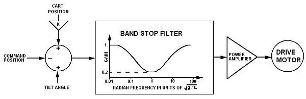
- Like time to carry a load by a crane, there is a peak in angular frequency ωp = √ g/ℓ of the pendulum for the reply of the non-handstand pendulum hung by the exercising fulcrum. It is necessary to control a frequency spectrum of the fulcrum motion near ωp to prevent uncontrollable vibration. With the handstand pendulum, a similar filter is necessary for stabilization.
As a result of null angle abnormality strategy, the position feedback becomes the equilateral feedback, and the cart moves to the right when I order the right suddenly to work to equilibrate the pendulum which inclined to the right after at first I move to the left again. The system becomes stable, and it becomes the profound problem by interaction with the instability of the handstand pendulum and the instability by the equilateral position feedback with fascination to analyze this mathematically.
Lagrange equation
I can derive an exercise equation from Lagrange equation. Like a forecited figure, I assume θ(t) the displacement angle from the vertical position of the pendulum of length ℓ and do the power to act with gravity and external force F to the x direction. Raglan sleeves diAnn L = T-V of the system can write that I define x(t) as the position of the cart as follows.

v1 assumes v2 the speed of the mass point of mass m the speed of the cart here. I can write v1 and v2 as x using a derived function of θ as follows.


I am as follows when I develop an indication method of v2.

Then raglan sleeves diAnn can write it as follows.

Here, the exercise of oiler Lagrange equation is the next indication method.


Equation system to describe the motion of handstand pendulum is provided as follows when I substitute an upper indication method for L in this equation system.


This equation system is non-linear, but often makes it linear shape θ≈0 around because an aim of the control systems is to keep a pendulum standing straight.
The second law of Newton
In substitution for Lagrange equation, there are often many advantages the Newton using the second law. A pendulum and the reaction force in the node between the cart are provided if I use Newton equation. Then in total two equations of x direction and the y direction are provided about each object. The motion of cart equation is as follows. But the left side of a go board cooperates, and the right side expresses acceleration.


Here, Rx and Ry express the reaction force in the node. FN is a vertical drag to depend on a cart. Because the second equation depends only on the reaction force of the plumb direction, I can use it to solve a vertical drag. I can use the first equation to solve a horizontal reaction force. It is necessary to calculate the acceleration of the mass point fixed to a pendulum to complete this exercise equation system. I can express the position of the mass point in the inertial coordinate system as follows.

I obtain an acceleration vector in the inertial system by taking the second-floor differential calculus.

Using a second exercise law, I obtain two equations of x direction and the y direction. It should be noted that it is for a reaction force and the reverse mark that the reaction force to depend on a mass point depends on a cart. This comes to the conclusion from the third law of Newton.


A method to calculate a horizontal reaction force is provided without stopping at external force F from the first equation. I can use the second equation for the calculation of the reaction force of the plumb direction. The first exercise equation を I substitute に and am provided as follows.
I understand the thing that is the same as the equation by the Lagrange method if I see this equation well. It is necessary to take the exercise equation of the pendulum and the dot product with the unit vector always at right angles to the pendulum to get the second equation. This vector is often called x coordinate of the object system. This vector is expressed using simple two-dimensional coordinate transformation in the inertial coordinate system as follows.

The motion of pendulum equation which I wrote by vector notation のようになる. The left side of a go board of the exercise equation to demand is as follows when I take the dot product with this statement and (I warn that it becomes the dot product when I reject it probably because I take the dislocation).


The expression of relations with an object system ingredient and the inertial system ingredient of the reaction force is used in the upper expression development. It is thought that this stick does not convey at all the load that is perpendicular to oneself from the supposition that a stick to tie a mass point and a cart to does not have mass toward. Therefore, merely write the object system ingredient of the reaction force like Rp , and it can say that only the ingredient along the stick exists. From this, the next equation is provided about the tension of the stick.

Similarly, I can calculate the right side of the exercise equation to demand by taking an expression of acceleration a → P/I which I showed earlier and the dot product with . The result is as follows (when I arrange it a little).

When I connect the left side of a go board and the right side and break it in m, I get the following.
This is the also same as the equation by the Lagrange method. All reaction forces are clear, and there is the advantage using the Newton method at the point that can guarantee that there is not destruction.
Pendulum to vibrate of the fulcrum
A cart can derive the motion of pendulum equation tied to the vibrating stand without the mass in the same way as the pendulum which was able to be connected. In this case the position of the mass point is expressed as follows.

And speed is provided by taking the first-floor differential calculus of the position.

Raglan sleeves diAnn of this system can write it as follows.

And it is oiler Lagrange equation

A motion of から next equation is provided.

When y is expressed in simple oscillation y = A sinωt, here, I obtain the next differential equation.

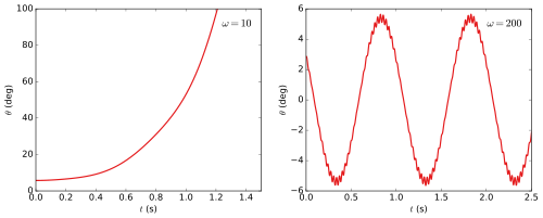
This equation does not have the fundamental solution of the shut form, but can check it by various methods. For example, precision is good and can be similar by Matthew equation when the amplitude is small. If vibration is fast, by analysis, I understand that a pendulum keeps standing straight. 下図のプロットの一つ目は y の振動が遅い場合には振り子を直立状態からずらすとすぐに倒れてしまうことを示している。 短時間で θ は 90°を超えており、つまり振り子は倒れてしまっている。 y の振動が速ければ振り子は直立位置の周りで安定に保たれる。 二つ目のプロットは振り子が直立位置 (θ = 0) からずれてもその近傍で振動することを示している。 直立位置からのずれは小さくたもたれ、倒れてしまうことはない。
倒立振子の種類
倒立振子を安定させることは広く取り組まれている工学的課題である[5]。台車駆動型倒立振子にも、棒を載せただけのものから振り子が複数の節に分かれているものまで様々な変種がある。その他にも、倒立振子の棒もしくは節分けされた棒を回転部品の端にとりつける種類のものがある。台車型と回転型のいずれの場合でも、倒立振子は平面内でしか運動しない。平衡位置にある倒立振子を維持するのが課題である場合もあれば、自律的に平衡位置を達成することが求められる場合もある。また、二輪倒立振子という別のプラットフォームもある。二輪倒立振子では一点での回転が可能であり、格段に高い操作性を実現できる[6]。その他にも、一点上での平衡をとるものもある。コマや 一輪車、ボール上の倒立振子はすべて一点上で平衡をとる。上で説明したように、鉛直に振動する台によっても倒立振子を安定化することができる。
倒立振子の例
倒立振子には人造のものも自然のものも含めて様々な例がある。
最も身近な倒立振子はヒトであるといわれる。直立した体を持つヒトは、常に平衡を保つための調整を行なっていなければ立つことも歩くことも走ることもできない。
単純な例として、箒や定規を手の上で直立させる遊びが挙げられる。
倒立振子は様々な装置に組込まれており、また特異的な工学的問題として研究されている[7]。倒立振子は本質的に不安定なので擾乱に対して計測可能な応答を示すため、初期の地震計の設計における中心的要素として採用されていた[8]。
倒立振子模型はいくつかのパーソナルモビリティにも採用されている。二輪車椅子やその他の二輪モーター車両により高い移動性を確保することができる。
関連項目
出典
- ^ C.A. Hamilton Union College Senior Project 1966
- ^ "Inverted & Hanging Pendulum Systems". Soil Instruments. 2016年11月19日閲覧。
- ^ "浮き式傾斜計の鋼管傾斜計測への適用について" (PDF). 土木学会第58回年次学術講演会. (平成15年9月)
- ^ http://exploration.grc.nasa.gov/education/rocket/rktstab.html
- ^ http://robotics.ee.uwa.edu.au/theses/2003-Balance-Ooi.pdf
- ^ http://csuchico-dspace.calstate.edu/bitstream/handle/10211.4/145/4%2022%2009%20Jose%20Miranda.pdf?sequence=1
- ^ http://csuchico-dspace.calstate.edu/bitstream/handle/10211.4/145/4%2022%2009%20Jose%20Miranda.pdf?sequence=1
- ^ http://earthquake.usgs.gov/learn/topics/seismology/history/part12.php
関連文献
- Franklin, Gene; Powell, J. D.; Emami-Naeini, Abbas (2005). Feedback control of dynamic systems (5 ed.). Prentice Hall. ISBN 0-13-149930-0.
- 「現代制御理論を使った倒立振り子の実験」、『トランジスタ技術』5月号、CQ出版、1993年、 315-322頁。
- 「現代制御理論を使った倒立振り子の実験」、『トランジスタ技術』6月号、1993年、 367-373頁。
- 「現代制御理論を使った倒立振り子の実験」、『トランジスタ技術』7月号、CQ出版、1993年、 363-370頁。
外部リンク
- YouTube - Inverted Pendulum - Demo #3
- YouTube - inverted pendulum
- YouTube - Double Pendulum on a Cart
- YouTube - Triple Pendulum on a Cart
- A dynamical simulation of an inverse pendulum on an oscillatory base
- Inverted pendulum modeling with several control systems in Matlab
- Inverted Pendulum: Analysis, Design, and Implementation
- Non-Linear Swing-Up and Stabilizing Control of an Inverted Pendulum System
- Stabilization fuzzy control of inverted pendulum systems
- 倒立振子系に対する安定化制御
- ワンチップマイコンを応用した自立型倒立振り子
- Hello! MiP - YouTube
- 倒立2輪 新タイプ - YouTube
This article is taken from the Japanese Wikipedia Handstand pendulum
This article is distributed by cc-by-sa or GFDL license in accordance with the provisions of Wikipedia.
In addition, Tranpedia is simply not responsible for any show is only by translating the writings of foreign licenses that are compatible with CC-BY-SA license information.
0 개의 댓글:
댓글 쓰기