Strong wind (plane)
Kawanishi N1K1 strong wind

Strong wind (latter term production type with the thrust type single exhaust pipe) of Sasebo flying corps
- A use: Anti-plane battle
- A classification: Water fighter
- A designer: Shizuo Kikuhara
- A manufacturer: Kawanishi plane
- An operation person:
 Great Japanese Empire (the Japanese Navy)
 - Maiden flight: May 4, 1942
- The number of the production: 97 planes
- An operational start: December, 1943
- The operational situation: Military retirement
The strong wind (きょうふう) is water fighter of the Japanese Navy which Kawanishi plane developed in the Pacific War. As for the mark, N1K1, the code name on the allied powers side were almost Rex. Shizuo Kikuhara that the chief design engineer dealt with two sets of flying boats.
This plane was designed as the body which assumed an air battle a main purpose while being a seaplane, but the number of the production does not reach 100 because I lose time of the activity because development ran into difficulties, and the performance is disappointing, and the operation was difficult. Two sets of water fighters which made Zero fighter a seaplane as a pinch-hitter until this plane appearance were developed, but this leaves a lot the number of the production for the military gains as such. Locality fighter (land plane) glaring eyes were developed based on this plane, and 紫電改 which was an improved development type played an active part for the ambush of B-29 and the U.S. carrier carrier-based plane which hit Japanese soil for Great War last years more.
Table of contents
Development process
I decided the development of the full-scale water fighter for the purpose of securing until airport completion when I invaded and attacked from the results that the Japanese Navy used 95 sets of water spy planes in substitution for an ambush machine and an air raider at the time of China incident and gave an effect to in the South Sea Islands of command of the air and the short compensation of the carrier plane in (1940) in 1940. It was not unusual that a seaplane played a key role before World War I and performed a battle duty, but the bodies for observation and the reconnaissance duty were often found in World War II, and the development of the seaplane which could perform a full-scale air battle was the one of a kind which reflected circumstances of Japan at the time [1].
In September, 1940, the navy ordered the trial manufacture of this plane to Kawanishi who had abundant development experience of the seaplane as 15 trial water fighters. The summaries of demand specifications shown in the trial manufacture remit are as follows.
- Maximum speed: At an altitude of 5,000 meters more than 310 knots per an hour (574km/h)
- A flying range (time): With cruising speed more than six hours
- Armament: 20mm machine gun *2 and 7.7mm machine gun *2 or 13mm machine gun *2 and 7.7mm machine gun *2 or 7.7mm machine gun *4
- 爆装: 30 kg of bomb *2
When I compare these specifications with the Zero fighter 11 type which was just put to practical use in those days, I exceed it more than 30 knots (56km/h) at a speed, and the same class is as above by two-thirds, armament at a flying range. Briefly, you should have said that it was demanded that I made a seaplane of the performance same as a new star main force fighter particularly the demand of the speed was approximately unrealizable for a thing demanded from a seaplane (even the maximum speed of model machine (J2M1) of the thunder and lightning that development was carried out for the same period is 578km/h). As a result, the maximum speed of the finished body was less than a demand nearly 100km/h, but I performed the technical effort that I mentioned later in the development team led by the Shizuo Kikuhara engineer of Kawanishi and wrestled for development eagerly in order to meet a demand. In addition, it is produced development by Nakajima airplane, and two sets of water fighters made from a Zero fighter 11 type by the filler-like implication will play an active part in the Pacific War beginning of the game because a stormy voyage was expected as for the development of this plane.
Design

Kawanishi took in various new keys like the auspicious purple clouds which were the water spy plane which produced it experimentally in the last year, and was ordered to meet naval demand specifications. I explain below the characteristic every each body part.
- An engine and body shape
- Mars (output about 1,500hp) made in Mitsubishi was adopted as an engine of the available large horsepower in those days. In Mars, a diameter (1,340mm) was relatively big for fighter use of the thing which was high power, and the nose part which located an engine was expected when air resistance grew big with the style of the normal single-engine fighter which became biggest. Therefore Kawanishi paid the attention to a fusiform body shape like the thunder and lightning that carried Mars in the same way. If it was the body with the same maximum product to cross-sectionalize by the wind tunnel experiment of the naval shipyard at the time, body center gathering was a point of the drag reduction, and there was a result to be advantageous, and the greatest position applied it to the fusiform body [2]. The engine was located nearer the body center to assume it spindle shape, and the cowl front was squeezed, and the propeller shaft was extended for clearance from the engine which I thereby produced to the cowl anterior extremity. This was a measure like the thunder and lightning, but the engine cooling fan to make up for the air mass flow from a narrow cowl opening equipped with by the plane was not equipped with.
- The main wing
- The middle wing placement that the main wing of the strong wind had little interference resistance with the body and spray of the water was hard to hit during a run was adopted. In addition, a laminar flow wing was adopted as the wing section. I delayed the detachment of the current of air on the wing with the laminar flow wing and it was the wing section which decreased air resistance and was expected when a speedup was effective. The thing of various shapes was studied, and the laminar flow wing was adopted to some warplanes (P-51 or brightly colored cloud), but the thing adopted for a strong wind was the LB type laminar flow wing which Ichiro Tani professor of Tokyo Imperial University (existing Tokyo University) invented in those days. The wing had a sectional maximum thickness position near 30% of the boom, but there was the maximum thickness position of the LB type laminar flow wing at approximately 40% of positions of the boom, and it was usually in the shape that current of air speed increased to wing posterior border (a wing of auspicious purple clouds is this LB type laminar flow wing). In addition, the smooth degree of the wing surface must be high, but there is the opinion that it might be difficult to realize precision necessary by the industrial arts at the time so that a laminar flow wing shows the effect.
- Flap
- Kawanishi developed the automatic air battle flap which operated an F ura flap at the most suitable angle according to speed and load automatically to do the battle with a land plane and the carrier-based plane in kineticism particularly turning characteristics profitably. This was Kawanishi's original invention to enable the self-regulation of the flap using a container (kind of Mano meter (liquid column manometor)) which I put mercury to detect dynamic pressure and load in. The strong wind relatively had a big loading to realize rapidity, but succeeded in acquiring turning ability not to fall behind two sets of small water fighters of the loading by this automatic air battle flap either. In addition, the device equipped with for a strong wind was a trial product, and a thing finished more was put on glaring eyes and 紫電改.
- Float
- Two sets of floats were comprised of the main float under the body and the supporting float under both main wings like water fighter. The main float was supported with the small V-shaped prop of the divergence in the front, and backward, thickness was supported with a wide prop thinly in the axis direction, and it was the shape that reduction of the air resistance was conscious of each (as for this, front and back are reverse to the placement of the prop of two sets of water fighters). The supporting float was considered for the gaining over-style plan like auspicious purple clouds at first, but it was said that it was rigid to receive the trouble in the plane, and to avoid complexity of the mechanism.
- Propeller
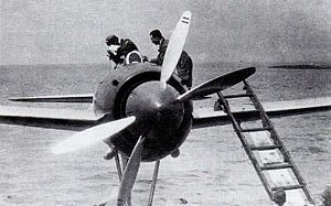
- For the inclination-related cancellation of the body by the spiral prop wash, I assumed the propeller of 2 feathers the set in two back and forth, and two folds of inversion propellers which reversed it each, and offset the torque by the race were adopted to a model machine of the strong wind. A detached room water landing became easy, and drivenness, the direction stability was good, and the reputation from a test pilot was very good, but the maintenance-related badness and oil leak to come were in this way changed to 3 normal feather propellers with the mass production type by the complexity of the propeller slowdown machine without dissolving. But a gap was left for the position where the second piece propeller should have been located with the production type in the first half year, and it was the characteristic appearance that a propeller spinner protruded from a cowl opening on the front.
- In addition, as for the thing produced later, a meeting-type exhaust pipe was checked to a thrust type single exhaust pipe, and cowl anterior extremity was extended again, and the rear of the propeller spinner which there was of the redundant space was covered with a cowl by a trace of the contraprop.
- In addition, the left torque of the "Mars" engine of liftoff output 1,460HP is strong and must handle a foot bar by considerable strength to deny it [3] and says that the detached room water landing was difficult [4].
Effect of the air battle flap
A navy aerodromics depot airplane part performs the experiment by the air battle flap from December, 1942 to February, 1943. The data recorded the process of the flight by a moving picture theodolite and they used a writing by oneself accelerometer together and were provided. Experiment altitude is 2,000m. As for the weight of the strong wind at the time of the experiment, 3,500 kg, loading are 148.9kg/ square m. Turning radiuses decreased to normal 70% - 80% when I used an air battle flap. The decrease of the turning time was not seen then. A diameter decreased about the somersault and decreased at time required for a somersault.
When a strong wind penetrated at 148 knots and circled, the load took 3.3G, and the turning radius needed 15.5 seconds at 180m, time. In contrast, as for the load, as for 4.1G, the radius, 140m, the time were 14.5 seconds when they penetrated at 151 knots and let a flap work at 19 degrees.
| Turning radius | ||||
|---|---|---|---|---|
| Use of flap (19 degrees) | Approach speed | Loading | Turning radius | Turning time |
| Unavailable | 148 knots | 3.3G | 180m | 15.5 seconds |
| Available | 151 knots | 4.1G | 140m | 14.5 seconds |
Similarly, I did it and measured a somersault.
When I penetrated at 190.5 knots and did not use a flap, the somersault diameter was 305m, maximum load 3.4G. It takes 11 seconds by the top of the somersault, and, as for the speed, 105.4 knots, load 1.65G, the high difference are 437m (from the point that penetrated). In addition, as for the time required for the somersault end, as for the high difference, -111m (from the point that penetrated), the speed were 184.5 knots for 23 seconds.
In contrast, the somersault diameter became 250m, maximum load 4.0G when I penetrated at 189.4 knots and performed a flap at 19 degrees. As for high difference 398m (from the approach point), speed, 95.5 knots, the load are 2.0G by the top of the somersault for 9.5 seconds. In addition, as for the time required for the somersault end, as for the high difference, 95m (from the approach point), the speed were 142 knots for 17.5 seconds.
In use, a high difference occurred 200m in nonuse time, and the speed drop at the time of the use of air battle flap was considerably big again [5].
| Somersault | |||||||||||
|---|---|---|---|---|---|---|---|---|---|---|---|
| Use of flap (19 degrees) | Approach speed | Somersault diameter | Maximum load | Top arrival time | Top speed | Top load | Start→ Top altitude difference | End time | Start→ End altitude difference | End speed | |
| Unavailable | 190.5 knots | 305m | 3.4G | 11 seconds | 105.4 knots | 1.65G | 437m | 23 seconds | -111m | 184.5 knots | |
| Available | 189.4 knots | 250m | 4.0G | 9.5 seconds | 95.5 knots | 2.0G | 398m | 17.5 seconds | 95m | 142 knots | |
Use, evaluation
As for the strong wind, it was adopted a regulation (1943) on December 21 in 1943, but the fight of the Solomon area was already settled by the victory of U.S. forces at the time and Japan advocated a desperate defense of the absolute national defense zone and went on the defensive, and a place of the activity of this plane developed for the purpose of invasion in the islands region hardly became extinct. It was such situation, but I am deployed and report B-24 of few things and patrol aircraft-shaped PB4Y and 撃墜破 of the B-29 to the seaplane corps that the strong wind presented it with regulation adoption in the Indonesian Ambonese island and Penang Island of the Malay Peninsula west coast offing. I seemed to often adopt the tactics to drop 30 kg of initiating-type bombs from the enemy plane upper part on the occasion of an anti-bomber battle in a period, and to give damage by the explosion. On the other hand, I was deployed in Sasebo flying corps and the Otsu flying corps (Lake Biwa) in Japanese soil and was included in an air defense duty, but there was hardly no war record [6]. I was used for 直掩 of the Operation others 1, Kikusui [7].
In addition, I enter into a battle in the form that 0 sets of one strong wind interfere F6F at war with the fighter in a warship off Tateyama, Chiba on February 16, 1945 and report one overthrowing after a fight war. That this is the only military gain that a strong wind gave for an enemy fighter [8].
That this plane loses appearance time after all, and two sets of water fighters which should have been originally the existence of the filler play an active part; have ended with a result. However, it may be said that the strong wind became the base of glaring eyes simply because there were such circumstances. 当時の海軍も強風が時局に見合わない存在であることを見抜いていたので発注数は予定より大幅に削減されたが、それは川西に事業の不振を懸念させ、本機を陸上機化した紫電の開発を促すことになった。 紫電とその改良発展型である紫電改は層流翼や自動空戦フラップといった本機の特徴を受け継ぎ、大戦末期に最後の奮戦を見せることになる。
強風の生産は川西のみが行い、総生産数は試作機を含めて97機であった。この内31機程が終戦時に残存していた。なお生産された全ての機体は強風一一型に分類されるが、紫電二一型を水上機としてフィードバックした強風二二型という派生型の開発計画があったとされている。
性能諸元(強風一一型)
- 乗員:1名
- 全長:10.58 m
- 全幅:12.00 m
- 全高:4.750 m
- 翼面積:23.500 m²
- 空虚重量:2,700 kg
- 最大離陸重量:3,500 kg
- エンジン:三菱 火星一三型 (空冷星型14シリンダー、離昇出力1,460hp)
- プロペラ:住友ハミルトン 油圧式可変ピッチ定速回転3翅プロペラ
- 最大速度:488.9 km/h
- 巡航速度:352 km/h
- 降着速度:131.5 km/h
- 航続距離:4.8時間
- 実用上昇限度:10,560 m
- 上昇力:4,000 mまで4分11秒
- 武装:九七式三型改二7.7mm機銃×2(装弾数各500発)、九九式二号三型20mm機銃×2(装弾数各60発)
- 爆装: 30 kg of bomb *2
保存機
強風は戦後に性能テストのため4機がアメリカに輸送されたが、そのうちの3機はほぼ全部品が揃った状態でアメリカに現存している。2015年5月現在の状態は以下の通り。
- 川西514号機 - メリーランド州スートランドの国立航空宇宙博物館付属ポール・E・ガーバー維持・復元・保管施設(en:Paul E. Garber Preservation, Restoration, and Storage Facility)でレストア待ち。
- 川西562号機 - テキサス州フレデリックスバーグのニミッツ博物館(en:Admiral Nimitz State Historic Site - National Museum of the Pacific War)で展示中。佐世保航空隊で使用されていたもの。
- 川西565号機 - フロリダ州ペンサコーラの国立海軍航空博物館でレストア待ち。
脚注
- ^ 他国でも水上戦闘機の開発がなかったわけではないが、既存の陸上戦闘機(F4Fやスピットファイアなど)を水上機化したものに過ぎず、しかも試作段階で開発が終了している。またイギリスのブラックバーン社ではB-44という引き込み式フロートを備えた水上戦闘機の開発計画があったもののモックアップまでしか作られなかった(岡部ださく 『世界の駄っ作機(1)』 大日本絵画、1999年、ISBN 978-4499226899、160頁参照)。空港を建設するための重機や空母を多数保有していたアメリカ軍にとってはそのような機体は有用性が薄く、イギリス軍においてはそもそも多数の島嶼を侵攻・占拠するという戦争を経験していないからである。また当然ながら性能も陸上戦闘機や艦上戦闘機に比べて格段に劣った。なお第二次世界大戦後にアメリカ海軍は港湾地区防衛というコンセプトの基にコンベア社にF2Y/XF2Y/F-7というジェット水上戦闘機を試作させたが、これも量産されることはなかった。
- ^ ただしこの実験結果はプロペラ後流の影響を考慮しておらず、それを勘案すると胴体を後部にいくにつれて引き絞った二式単座戦闘機やFw190に代表されるスタイルの方が有利であるという見解もあった。
- ^ 渡辺 2002, p. 135.
- ^ 渡辺 2002, p. 136.
- ^ 海軍航空技術廠 『研究実験成績報告(空技報0358) 空戦フラップニ関スル研究(其ノ1)(15試水上戦闘機) (飛行機性能ノ研究第44回報告) 』
- ^ 渡辺 2002, pp. 136-140.
- ^ 渡辺 2002, p. 144.
- ^ 渡辺 2002, p. 142.
参考文献
- 文林堂編集部 『世界の傑作機 No.124 強風、紫電、紫電改』 文林堂、2008年、ISBN 978-4893191588
- 海軍航空技術廠 『研究実験成績報告(空技報0358) 空戦フラップニ関スル研究(其ノ1)(15試水上戦闘機) (飛行機性能ノ研究第44回報告) 』昭和18年。アジア歴史資料センター A03032133000
- 渡辺, 洋二 (2002), "去りゆく水戦", 遙かなる俊翼, ISBN 4-16-724914-6 - 初出は『航空情報』1982年3月号
関連項目
This article is taken from the Japanese Wikipedia Strong wind (plane)
This article is distributed by cc-by-sa or GFDL license in accordance with the provisions of Wikipedia.
In addition, Tranpedia is simply not responsible for any show is only by translating the writings of foreign licenses that are compatible with CC-BY-SA license information.
0 개의 댓글:
댓글 쓰기