Orbit circuit
Orbit circuit (you come, and please be) is an electrical device to detect whether there is a train in the specific section on the track in a railroad. I use it to move a signaling device for confinement.
Table of contents
Principle
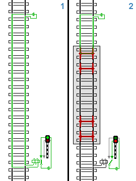
The left: When a train does not perform a living-in-flight, an electric current flows in a relay, and a relay does 扛上
The right: When a train performs a living-in-flight, an electric current does not flow in a relay, and a relay drops
The basic principle of the orbit circuit is that a wheel and the axle of the vehicle shunt two rails and constitute an electric circuit. I attach a device to this electric circuit and detect the existence of the train. I call that there is a train in the section of the track a living-in-line.
Because orbit circuit is a security device, it is very important that it is failsafe. The which fails in detection though a train does a living-in-line is in a dangerous condition than I detect it in preservation by mistake though a train does not perform a living-in-flight. Therefore, it is designed to become "the state that a train detects a living-in-line" of the safe side when orbit circuits usually break down. On the other hand, it is desirable for what it detects by mistake when a train performs a living-in-flight that being able to do such a thing prevents it from occurring to inhibit the service of the railroad.
Constitution of the circuit
The orbit circuit is constructed by a relay set up between power-supply unit and the rail which supply an electric current to a rail. Each orbit circuit comes to detect a living-in-line in the range of the identification such as 1 section of the confinement. If it is not non-insulated track circuit to mention later, the detective sections of the orbit circuit are insulated electrically each other.
By the orbit circuit of the section without the divergence, I can make a position of the insulation of the rail of both sides agree in the border, but, as a result, the section that I cannot detect as orbit circuit occurs because a gap produces a position of the insulation of the rail of both sides in the border from the assembling of the rail of the turnout by the orbit circuit of the section with the divergence without agreeing without both rails being able to short-circuit in homopolar neighbor wheel and axle electrically. Call this death space; for the length and position relations with the limit [1].
I attach a power supply to one edge of the orbit circuit section and apply the voltage between both rails. I get a relay on the contralateral edge of the orbit circuit. When a train does not perform a living-in-flight in the section, the electric current which flowed from a power supply through a rail operates a relay (a relay makes it 扛上 (こうじょう)). When a train performs a living-in-flight, a rail is shunted by the wheel and axle, and an electric current does not flow in a relay (a relay drops). In other words, I will express it whether a relay does 扛上, or you drop whether a train does a living-in-line in the section. [2]
The orbit relay is a switch working by an electric current, but there is it so that probability of the trouble remaining in a state that I made 扛上 by gravitational work extremely in comparison with probability of the trouble remaining in a state that dropped lowers. Therefore, it is custom to design so that the state that dropped supports the living-in-line of the train which is a safe side.
The orbit circuit detects having train or not by short-circuiting by the wheel and axle of the vehicle electrically between rails, but, between a wheel and axle and the rail, 車輪踏面 and electrical resistance called the short circuit resistance by two places of contact resistance between the rail and axle resistance of the wheel and axle occur. I stop by at the time of train runs such as at the time of train weight or power running, 惰行, braking and it is different and is less than 60 microhms by the interchange and, in the contact resistance, is said to be lower than 100 microhms by the direct current. A train is low at power running or the braking, and the short circuit resistance is high in 惰行時. In addition, the short circuit resistance tends to become higher because rust occurs in the rail top surface when I receive spray of the seawater in fine weather after rain and a coastal route in night service stop time. In addition, I call the biggest short circuit resistance that a relay falls to in the biggest resistance when I short-circuit between rails with short circuit sensitivity, and the unit is expressed in Ω.
In the case of ballast, in the case of concrete or orbit slab, the rail constituting orbit circuit is fixed to the top on the railroad tie in roadbed and is exposed. That purpose, rain when it snows, a rail and ballast get wet, and the lower part will include water, too, and, as a result, the electric current of the orbit circuit drifting to the rail leaks, and the electric current of the orbit circuit consumes it; is in a condition. I use leak resistance to express "leak resistance around 1km" as a thing indicating the degree of the leak. Leak, and the resistance is high, but, in the case of rain and an intense heavy rain, it becomes 1 Ω from 10 Ω, and, in the case of fine weather, it decreases to 0.1 Ω from 0.5 Ω with 50 Ω when intense leak of water and seawater invade in a tunnel. When I leak, and resistance decreases, the electric current of the orbit circuit leaks on the way, and a train adjusts the voltage to hang in the orbit circuit to the orbit circuit in consideration of roadbed conditions such as the ballast because an absent case and train pass it, and there is fall してまう fear, and a relay prevents it when I am absent.
There is orbit transformer, divider by a silicon rectifier, lead storage battery, the interchange by the direct current, and, in real orbit circuit, there is the lap device that orbit relay (relay) doubles on the side to receive of the side receiving the electric current from a rail [3] on the transmission side of the side applying an electric current to a rail. In addition, when when connect a power supply to the rail of the orbit circuit directly, shunt the transmission side in a wheel and axle; of the shortstop when a return wire electric current drifts to the side apparatus which the transmission receives when a rail broke in resistance and reactive coil for current-limiting to prevent an electric current above a certain level from drifting, the orbit resistance child who adjusts the voltage to receive from a rail to the appropriate voltage to orbit relay in a side receiving a side, single rail type orbit circuit to be in a condition, and to prevent that an unreasonable electric current drifts, and destroy a power supply apparatus, and concentrate on an apparatus room, and install the side apparatus which orbit fusibility piece, orbit fuse, the transmission to prevent blowout or the one which let damage by a fire, and signal equipment and an interlocking device stop receive, there is a broadcast transformer to reduce the voltage drop with the cables from an apparatus room to the transmission edge or the edge to receive, and give you a duty to operate orbit circuit surely, and to protect.
Kind of the orbit circuit
A classification and kind caused by the signal electric current
The electric current applied on a rail by orbit circuit has direct current and interchange. Furthermore, by the interchange, various frequency is used and can use it properly depending on the condition of the use place. I show below a classification and the kind of the Japanese orbit circuit used by rail.
DC track circuit
In the DC track circuit, the signal electric current flowing in a rail is direct current. I usually reverse polarity by the neighboring orbit circuit to prevent what the electric current of the neighboring orbit circuit flows when the insulation was spoiled and detects mistakenly. For a blackout, the low voltage (from 1.5V around 12V) using the battery is used for orbit circuit.
- DC track circuit
- I connect a battery to the transmission side and charge it by a floating charge method [4], and no blackout plans making it it so that I drain the DC power supply which converts it into a rectifier, and was done on the transmission side by a commercial frequency power supply into the orbit circuit and receive it on the transmission side and input it into orbit relay (relay) for the direct current, and facilities constitution is easy, and a cost of equipment operates at the time of the blackout again cheaply. It is 4.5V and can use the voltage between the rail by orbit circuit to 800m, but, on the other hand, there is a problem of the maintenance of the battery. I am used in non-electrified section and the return wire electric current of the electric car becomes the interference in the direct current electrification section and cannot use it. Furthermore, I may receive interference by the electricity usage situation of the neighborhood.
- H, DC orbit circuit
- In non-electrified section, is used by the yard orbit circuit in the specially automatic occlude expression, and H high; is a meaning of electricity, the high short circuit sensitivity, and the voltage between the rail is 12V of approximately 3 times of the DC track circuit. Therefore a big short circuit electric current (4-5A) flows at the time of the short circuit between the rail in the wheel and axle, and high short circuit sensitivity comes to be provided. For yard orbit circuit use, the length of the used orbit circuit is 50m briefly in 300m, an open track circuit (I call it the OT orbit circuit) in a closed track circuit (I call it the CT orbit circuit).
Interchange orbit circuit

By the interchange orbit circuit, the signal electric current flowing in a rail is interchange, and, as for the frequency, a low frequency (number 100Hz or less), audio frequency (number 100Hz - number kHz), a high frequency (more than number kHz) vary depending on a purpose. In addition, there is the orbit circuit applying an electric current pulsingly.
- AF orbit circuit
- I use audio frequency, and Audio Frequency is called AF for short. I am used in some ATS using ATC and the orbit circuit.
- Commercial frequency orbit circuit
- I divide a power supply for the electricity of commercial 50 or 60Hz frequency and use it. I am used in a direct current electrification section and show a figure of model of the circuit on the right side. In the case of the automatic signal of the 2 yuan third place type (I display 現示 of the signal with green, yellow, red by changing the state of the orbit relay into three with two kinds of power supplies), there are two relays of 緩動継電器 and the orbit relay in the control circuit of each signal, and orbit relay detects an interchange electric current drifting to the rail of the orbit circuit and controls a signal [5]. Parallel installs the high pressure power line for the signal of single-phase alternating current 3,300V in the rail to make phase of the frequency of the interchange electric current on the transmission side and the reception side of the orbit circuit agree with supplying power and lets wiring separate from a power line with each confinement signal. After having let 110V depress it by line Jo transformer, I drain the interchange electric current to apply in orbit circuit into 18V by orbit transformer more via the point of contact of 緩動継電器 after I am depressed, and the power supply of the signal lamp of the confinement signal is used for 30V with a signal lamp transformer from the 110V power supply for the orbit circuit after having depressed it.
- 右側に制御回路のモデル図を元に現示の仕組みを説明すると、前方の軌道回路からレールに流れる通常の電流を軌道継電器が検知すると、接点が左方接点となり、その後、緩動継電器が扛上して上方接点となり、後方の軌道回路に、通常の位相の電圧を送る場合には、信号機は緑を現示し、前方の軌道回路で、列車の輪軸によりレールに流れる電流を短絡すると無電圧となり、それを軌道継電器が検知すると、無接点(ブラ)の状態となり、その後、緩動継電器が落下して下方接点となり、後方の軌道回路に、位相が反転した電圧を送る場合には、信号機は赤を現示し、前方の軌道回路から送られた位相が反転した電圧を軌道継電器が検知すると、接点が右方接点となり、その後、緩動継電器が扛上して上方接点となり、後方の軌道回路に通常の位相の電圧を送る場合には、信号機は黄色を現示する。
- 分倍周軌道回路
- 送信側で、商用電源周波数を分周器により1/2に変換してから、軌道回路に25又は30Hzの交流電流を流し、受信側でその周波数を倍周器により元の周波数に戻して、その後、軌道継電器に入力するものである。その為、軌道継電器には商用周波数軌道回路専用のものを使用する。商用電源周波数である50又は60Hzを使用する交流電化区間や、それ以外の区間で特別高圧送電線が平行している場合に使用され、事故時における誘導電流による妨害電流が発生しても、リレーが確実に落下して列車を検知できるようになっている。
- 分周軌道回路
- 送信側で、商用電源周波数を分周器により1/2に変換してから、軌道回路に25又は30Hzの交流電流を流し、受信側でその周波数を受信して、その後、軌道継電器に入力するものである。駅などの大きな構内で使用されており、元々は、そこで分倍周軌道回路を使用すると、軌道回路数が多い分、その数だけその機器を置くスペースがかなり必要となる為、その省スペース化を目的に作られたもので、変換された周波数を各軌道回路に送る為、大型分周器を使用しており、軌道継電器には分周軌道回路専用のものを使用する。
- 83/100Hz軌道回路
- 交流電化区間において、架線から電車や機関車のモーターに使用された後、車輪を経由してレールに流れる帰線電流や、それによる誘導電流に影響されない周波数である83Hzと100Hzを使用するもので、送信側でMG(Motor Generator、電動発電機)又はCVCF(Constant Voltage Constant Frequency、定電圧定周波数装置)で作られた83Hz又は100Hzの交流電流を、軌道回路に流し、受信側ではそれを受信して軌道継電器に入力するものである。交流50Hz区間では83Hzを、交流60Hz区間では100Hzの電源周波数を使用しており、その為、軌道継電器には2元型の83/100Hz軌道回路専用のものを使用する。交流電化区間や軌道回路に誘導電流による誘導妨害を受ける区間において、駅などの大きな構内で使用される。
- H・AC軌道回路
- 直流電化区間や交流電化区間において、特殊自動閉塞式での構内軌道回路で使用されているもので、H・DC軌道回路の交流型である。開電路式軌道回路と閉電路式軌道回路ともに、送信側で、送信器により直流24Vから交流80Hzに電源を変換してから、軌道回路に流し、受信側でそれを受信して、その後、軌道継電器に入力するもので、軌道継電器には2元型で80Hz専用のものを使用する。
- 長大軌道回路
- 長い軌道回路において、中間に閉塞信号機を設置せず、単線自動閉塞方式に使用されているもので、非電化区間では6km、直流電化区間では5kmまでの制御か可能である。送信側で分周器により商用電源周波数を1/2に変換して、軌道回路に25又は30Hzの交流電流を流し、受信側で専用の信号受信機で受信して、その後その交流電流を整流し直流に変換してから、直流用の軌道継電器に入力するもので。送信側と受信側で交流電流の周波数の位相を一致させる必要がない為、今までの交流軌道回路と違い、高圧配電線の設置を必要としない。
システム構成による分類
閉電路式軌道回路
原理の項で説明したように、列車を検知するリレーには列車が在線していない時に信号電流が流れ、在線している時には電流が流れなくなるようにシステムを構成するのが標準である。こうした回路を閉電路式 (close circuit) と呼ぶ。これは電源の故障、レールの破断、ケーブルの破損など、考えうる様々な故障の際にも電流が流れなくなるフェールセーフ構成としているため、故障時でも在線として検知するようになっている。
開電路式軌道回路
閉電路式に対して、列車が在線していない時には電流が流れず、在線している時にだけ電流が流れる方式の回路を開電路式 (open circuit) と呼ぶ。開電路式では、電源と検知用のリレーを直列に接続したものを線路の同じ側につなぎ、列車が進入することで車軸が両側のレールを短絡して電流が流れるようになっている。この回路は、電源の故障、レールの破断、ケーブルの破損などで1箇所でも故障すると電流が流れなくなって列車を検知することができなくなるため、フェールセーフ構成とはなっていない。そのため、列車を誤って検知することが、検知に失敗することより危険になるような場合や、踏切の保安装置での点制御方式において、終止点での列車検知に利用される場合では、こうした軌道回路が用いられる。
帰線電流路による分類
ほとんどの電気鉄道では、架線または第三軌条から走行用の電力を集電してレールから変電所に戻している。レールを通って変電所に戻る電流を帰線電流と呼ぶ。このため、信号電流と帰線電流を明確に区別する必要がある。さらに、軌道回路境界において信号電流のみを絶縁して帰線電流を流す仕組みが必要となる。
信号電流と帰線電流を区別するためには、双方の周波数を異なるものにすることで対処している。例えば、直流電化区間に交流軌道回路を設置して、リレーが信号電流の周波数のみを検知するようにインピーダンスポンド又はフィルタ回路を取り付ければ、直流の帰線電流が軌道回路を誤動作させるおそれは少なくなる。また、交流電化区間では交流軌道回路を用いることができないわけではなく、帰線電流と違う周波数を信号電流に使えば使用できる。
軌道回路境界で帰線電流のみを流す仕組みとしては複数の方式がある。
複軌条軌道回路


複軌条軌道回路では、両方のレール共に隣の軌道回路との境界に絶縁が行われている。絶縁は、レールのつなぎ目に絶縁板を挟み込むことで行われている。このつなぎ目を絶縁継目という。直流軌道回路では絶縁継目のみで隣の軌道回路との境界を作ることができるが、直流電化区間又は交流電化区間では、軌道回路との境界を越えて帰線電流を流すためにインピーダンスボンドが用いられている。
右側にあるインピーダンスボンドの配線図を元に説明すると、インピーダンスボンドには、レールに接続された1次側コイルと軌道変圧器又は軌道継電器に接続された2次側コイルの2つの巻線があり、2つのコイルの間は、変圧器と同じく鉄心により結合されている。インピーダンスボンドの間は、中性線により1次側コイルの中性点で結ばれている。列車で使用された帰線電流であるI1とI2はレールからインピーダンスボンドの1次コイルの中性点に流れ、中性線を経由して、隣のインピーダンスボンドの1次コイルの中性点に流れた後、レールに戻り流れていくが、中性点では両側にあるレールからのコイルの巻線が同一であるため、コイルに発生する磁束が打ち消し合い、2次コイル側には電圧は誘導しない。だが、信号電流であるIsは、一方のレールから1次コイルを経由して、もう一方のレールに流れるため、2次コイル側に電圧Esが誘導される[6]ようになっており、信号電流の周波数のみを遮断して帰線電流のみを流すようになっている。
右側の写真では、両側に見える黒い箱の中に1次側コイルと2次側コイルが入っており、黒い箱同士を結ぶ線が中性線で信号電流を遮断して帰線電流のみを流している。場合によっては、この中間線の間で変電所や負饋電線への線を接続して帰線電流を吸い上げている。軌道回路境界のインピーダンスボンドではこのように2つの箱を使用することが多いが、箱を1つだけ設置して変電所へ帰線電流を吸い上げる仕組みになっている場所もある。なお、軌道回路境界ではないレールのつなぎ目では、レールの隙間による電気抵抗の増大を防ぐために、レールボンドと呼ばれるワイヤがレールの側面に取り付けられて、信号電流を確実に流すようにしてあることがある。
単軌条軌道回路
単軌条軌道回路では、片側のレールにだけに絶縁継目を行う。信号電流は絶縁されていない一方のレールと絶縁されているもう一方のレールの両方に流れているので、片側だけレールを絶縁するだけでも外部への漏洩を防止できる。一方、帰線電流は絶縁されていない側のレールを流れて変電所へ戻る。また、絶縁されている側のレールを信号側レール、されていない側のレールを帰線側レールと呼んでいる。そのため、インピーダンスボンドは設置しなくてもすむが、帰線側レールが破断してしまうと帰線電流が流れなくなり、電気による列車運転ができなくなる短所がある。
無絶縁軌道回路
無絶縁軌道回路は、区間により信号電流の周波数を違えることによって区間ごとの絶縁を不要にするものである。隣の区間の軌道回路の電流が流れ込んでも、フィルタにより遮断されるので誤検知することはない。電源からの距離が離れると信号電流が減衰して車軸による短絡を検知できなくなるので、減衰を考慮して検知範囲を設定する。無絶縁軌道回路を用いれば、電気鉄道におけるインピーダンスボンドを不要にすることができる。絶縁継目は軌道構造上の弱点となっており、破損が発生しやすいため、これを廃止できることは無絶縁軌道回路の長所である。
無絶縁軌道回路には、軌道回路境界を共振子や電線で短絡する境界短絡式と多くの周波数を使用して境界を構成する多周波式があり、両者とも送電端から特定の周波数の信号電流を流し、受電端でその周波数に合わせた特性で受信して軌道回路の短絡を検出する。その周波数の電流が受電端を越えて隣の回路に流れ込んでも、その回路では異なる周波数に合わせてあるので誤検知することはない。いくつかの軌道回路を挟んで再度同じ周波数の信号電流を使用するが、間に十分長い距離があればその間に信号電流が減衰するので、同じ周波数を利用している他の軌道回路と混信することもない。ヨーロッパなどでは、特定の共振周波数に合わせたフィルタ回路を受電端側に接続することで、完全に隣の軌道回路への信号電流の漏れを防ぐ仕組みを採用しているところがある。
Aster SF15型の軌道回路では一方の線路で1700Hzと2300Hz、もう一方の線路で2000Hzと2600Hzの信号電流を用い、これを低周波で変調している。
TI21型軌道回路では以下のような周波数を使用している。
| A | 1699 Hz | 下り線 |
| B | 2296 Hz | 下り線 |
| C | 1996 Hz | 上り線 |
| D | 2593 Hz | 上り線 |
| E | 1549 Hz | 下り線 |
| F | 2146 Hz | 下り線 |
| G | 1848 Hz | 上り線 |
| H | 2445 Hz | 上り線 |
AからDが複線区間で用いられ、EからHは複々線区間用の追加の周波数である。
情報送信機能
軌道回路を利用して情報を列車に送信することがある。信号電流に符号(コード)を重畳して送信するもので、コード軌道回路と呼ぶ。コードの重畳には信号波の断続を利用したり、信号電流を用いて変調したりする。主に車両に搭載された車上子でコードを受信して、車内信号を実現するために用いられる。
使用
軌道回路は、以下のような目的で使用される。
- 列車の在線状況に応じて自動的に信号機に注意現示や停止現示を出し、列車の追突や正面衝突を防ぐ。
- 停車場構内での列車の位置を検知し、連動装置を動作させて安全を守る。
- 分岐器や跳ね橋などの可動する装置に列車が差し掛かっていることを検知し、列車が完全に通過するまでそれらの装置が動かないように鎖錠する。
- 踏切への列車の接近を検知して踏切警報機と遮断機の動作を開始させ、列車の通過を検知して動作を終了させる。
- 交流電化区間で異なる変電所からの供給区間を分ける異相区分セクションを力行したまま通過できるようにする饋電区分切替セクションにおいて、列車の現在位置に応じて饋電を切り替える。
使用目的に応じて軌道回路の長さや信号周波数は様々に調整される。また、同じ線路の区間で複数の軌道回路を、周波数を違えて設置する場合もある。
踏切を列車が通過したことを検知して警報機や遮断機の動作を終了させる軌道回路では、誤って列車の在線を検知すると列車の通過前・通過中に警報機や遮断機の動作が終了する危険な状態となるため、通常とは逆に開電路式の軌道回路を使用することがある。列車の進行方向が限定される複線区間では踏切の制御回路は単純であるが、単線である場合や単線並列である場合は、列車の進行方向に応じて検知する場所を変える必要があり、複雑な構成となる。さらに高度な仕組みでは、列車の速度や列車種別に応じて列車側から踏切制御回路に情報を送信し、警報の動作開始点を変えるようになっている。ATACSでは、踏切の制御を車上から行えるようになり、踏切制御の軌道回路は不要となる。
饋電区分切替セクションは、新幹線において用いられている。
軌道回路は区間の一方の端から電流を流して反対側の端で検知するので、導体となるレールが破損して信号電流が流れなくなると在線状態となる。事故や災害、保線の不良などによりレールが破断した場合でも自動的に信号機が停止現示となって列車の進入を防ぐことができる点も、安全に寄与している。
保線用車両の中には、信号機の誤動作を防ぐために両側の車輪を故意に絶縁して、軌道回路に検知されないようにしているものがある。こうした車両は信号システムと互換ではないため、使用する際には線路閉鎖を行って他の列車の進入を防ぐ必要がある。また踏切の警報装置が動作しないため踏切の通過には注意を必要とする。
回路の故障
たいていの故障では、列車が在線していると検知するように設計されている。
- レールや電源・リレーに関するケーブルが破損するとリレーが落下する。ただし下記の例外を参照。
- 電源供給が絶たれるとリレーが落下する。
- 軌道間の短絡や、他の軌道回路区間との短絡が起きるとリレーが落下する。
一方で、列車の在線検知に失敗する故障もある。
- リレーが扛上(列車が在線していない)した状態に固着して動かなくなるような、物理的な故障をした場合。
- レールの錆や砂、乾いた落ち葉などがレールの上にあり、車輪との間を絶縁してしまった場合。軌道短絡不良 (poor shunting) と呼ばれる。
- 線路周辺の環境により、妨害電流が流れ込む場合。例えば湿ったバラストが電池の働きをして電流を発生させたり、近隣の電力線から電流が流れ込んだりする。
- 電気抵抗が十分下がらない程度に車両が軽い場合や、そもそも両側の車輪が電気的に絶縁されている場合。
- レールが破損しても信号電流が流れ続ける程度の場合。
在線検知に失敗するような故障は、結果的に列車が在線している線路に他の列車の進入を許して事故の危険を招く。また踏切の警報機が動作しないという問題もある。このためイギリスでは車軸の検知装置も併用されている。
これらの故障に対処するために様々な手段が用いられている。例えば、リレーはとても高い信頼性を持つように設計されている。雑音電流の問題がある区間では、状況に合わせて雑音に強い軌道回路の方式が選択されている。落ち葉が問題となる区間では速度制限が設定されることがある。軌道短絡不良の問題が発生した場合には、列車を運休にする措置がとられることもある。
破壊工作もまた問題である。1995年のPalo Verdeでの脱線事故では、犯人はレールを取り除いた後に軌道回路の信号電流を通すためのワイヤを接続していた。このためレールがなくなっていることを軌道回路で検出できず、信号機は停止現示に変わらなかった。
回路状況の記録と伝送
軌道回路で検知した在線状況は、信号機や分岐器の状況と共に、指令センターの制御盤にまとめて表示されることが多い。軌道回路のリレーを通信回線に接続することで、在線状況を送信することができる。在線情報は制御盤に表示されると共に保存され、事故時の調査に用いられると共に、運行管理上の分析にも用いられている。多くの信号システムでは中央の指令センターでだけでなく各装置ごとに軌道回路の状況記録装置を持っている。
軌道短絡器
軌道回路によって線路閉塞を行っている線区では、列車の乗務員や線路軌道に立ち入る係員が携行する保安装置の一つとして軌道短絡器がある。これは2つの電極クリップ又は、磁石付電極板とその間をつなぐ電線からなる単純な器具で、イメージは自動車用ブースターケーブルの一本に似ている。列車事故や災害が発生した際に、軌道短絡器で両側のレールを短絡する(ショートさせる)ことで軌道回路に在線を検知させ、軌道短絡器を設置した箇所の外方(手前)の信号機を停止現示に変えることができる。例えば、複線区間で脱線事故が起きて対向の線路を支障した場合、軌道短絡器を対向線路に設置することで、当該現場へ接近する対向列車に対して停止信号を現示することができる。軌道短絡器を設置すると直ちに、そして自動的に停止現示に変えられるので、指令センターに連絡を取って列車を止めてもらうより早くて確実で安全である(ダイヤ上では列車はいないはずなのに、いる事になっている、というわけで指令所でも異変が起きた事がすぐにわかる)。特に、濃霧時、強雨時、急曲線箇所においては視認可能距離が極度に低下するので、携帯用合図旗や合図灯、携帯用信号炎管では接近する他列車乗務員へ非常停止指示を確実に伝達できない場合が生じるが、軌道短絡器を使用した場合は当該閉塞区間始点の信号機に「停止」が現示され、その一つ手前の閉塞区間始点信号機には「注意」又は「警戒」が現示されるので、高速列車が接近する場合の他、降雪時やブレーキ性能が劣る列車が接近する場合にも確実性が高い。
高機能なものとしては、照査装置のついた軌道短絡器がある。これは、軌道短絡の電気抵抗が一定以下になっていることをチェックして表示する機能が備えられている。さらに信号機を制御する信号電流のみを短絡して、踏切制御の信号電流は短絡しないフィルタ機能を備えていて踏切の動作に影響を与えない軌道短絡器も開発されており、主に保線作業で用いられている。
歴史
フェイルセーフな軌道回路は、1872年にアメリカの土木技術者、ウィリアム・ロビンソン (William Robinson) によって発明された。彼が軌道回路を発明したことにより、いまや世界中の鉄道で使用されている自動信号システムが可能となった。
当初の鉄道の信号機は、駅の係員や信号扱手によって手動で動かされていた。いつ信号の現示を変化させるかはしばしば扱い者に委ねられていた。ミスによりしばしば不正な現示を出して、事故に繋がった。
19世紀中ごろに電信が発明されて長距離を電気的に情報伝送できるようになり、電気的に制御された信号システムの開発が始まった。しかしながら、ロビンソンの発明以前に開発されたものはどれも、列車の動きに自動的に対応して信号現示を変化させることはできなかった。
ロビンソンはまず、1870年に完全自動の鉄道信号システムの模型を作成してデモを行った。続いてフィラデルフィア・アンド・エリー鉄道 (Philadelphia and Erie Railroad) のペンシルベニア州キンズア (Kinzua) で実物大のシステムが導入された。彼の設計したシステムは、信号機の上に電気的に動作するディスクを取り付けたものとなっていた。また設計は、列車が在線していない時に信号電流がなくなる、開電路式であった。
この設計の本質的な欠点は、フェイルセーフではなく簡単に危険な状態になってしまうことであった。例えばワイヤが切れると、列車が在線していても検知に失敗してしまう。この問題を認識して、ロビンソンは現代の軌道回路のような閉電路式のものを設計し、1872年に前述の場所に設置した。これが現代の完全自動化したフェイルセーフな信号システムの元祖である。
イギリスでは、1876年にウィリアム・サイクがクリスタル・パレス駅で軌道回路の実験を行ったのが最初となっている。実用化されたのは1886年で、ロンドンのセント・ポールズ駅に設置されたものであった。
日本においては、1904年(明治37年)に甲武鉄道(後のJR中央本線)の飯田町 - 中野間でアメリカのユニオン・スイッチ・アンド・シグナル社の技術により導入されたものが最初である。
事故
軌道回路がなかったために起きた事故
軌道回路があれば多くの事故が防げていたと考えられる。軌道回路がなかったために起きたと考えられる事故は以下のようなものがある。
- キンティンスヒル鉄道事故
- ホーズ・ジャンクション鉄道事故 (Hawes Junction rail crash)
軌道回路の故障により起きた事故
軌道回路の故障により起きた事故も、稀ではあるが下記のように存在している。
- コワン鉄道事故 (Cowan rail disaster) - レールの上に砂が載って車輪を絶縁したために軌道短絡不良が起き、不正な進行現示が表示されて追突事故を起こした。
- ビッグ・バイユー・カノー列車事故 (Big Bayou Canot train disaster) - 霧の中で艀が旋廻橋に衝突し、レールの接続が歪んだが、信号電流は絶たれなかったため信号が停止現示に変わらなかった。直後にアムトラックの列車がレールの歪んだ箇所に高速で進入して脱線し、水の中に転落した。
脚注
- ^ JRでは、死空間の長さを6020mm以下に制限しており、死空間同士又は隣接の軌道回路との距離は、死空間が1210mm以上では1500mm以上、死空間が1210mm以下では制限無しとしている。
- ^ この用語法は、鉄道用のリレーで特に使われているものであり、電気分野で一般に使われているものではないので一般の場合などに注意。
- ^ 一部の交流軌道回路のみ使用。
- ^ 供給を受けた電気を負荷が使用しながら、蓄電池に電気を充電する方式。
- ^ 軌道継電器は軌道コイルと局部コイルの2つのコイルを組合せた構造になっており、軌道コイルには軌道回路からの電圧、局部コイルには配電線からの電圧が繋がっており、2つのコイルの電圧の位相差により電力用積算電力計と同じ原理で軌道継電器の回転方向が変わり、それにより接点を切替える構造になっている。
- ^ 2次コイルに信号電流が流れる場合には、1次コイル側に電圧が誘導されて、レールに信号電流が流れる。
参考文献
- 菱沼 好章「鉄道業務セミナーNo.2 信号保安・鉄道通信入門」中央書院 ISBN 4-924420-61-1
- 江崎 昭「輸送の安全からみた鉄道史」グランプリ出版 ISBN 4-87687-195-7
- 久保田 博「鉄道工学ハンドブック」グランプリ出版 ISBN 4-87687-163-9
- 持永 芳文「電気鉄道技術入門」 オーム社 ISBN 978-4-274-50192-0
- 鉄道電気読本 改訂版 日本鉄道電気技術協会 ISBN 978-4-931273-65-8
関連項目
外部リンク
- 鉄道技術用語辞典 online - 鉄道総合技術研究所が提供する用語辞典。用語検索で「軌道回路」を検索すると、様々な軌道回路の説明が見られる。
- 株式会社テス 軌道短絡器 - 高機能な軌道短絡器。
This article is taken from the Japanese Wikipedia Orbit circuit
This article is distributed by cc-by-sa or GFDL license in accordance with the provisions of Wikipedia.
In addition, Tranpedia is simply not responsible for any show is only by translating the writings of foreign licenses that are compatible with CC-BY-SA license information.
0 개의 댓글:
댓글 쓰기