검색어 slowdown machine에 대한 글을 관련성을 기준으로 정렬하여 표시합니다. 날짜순 정렬 모든 글 표시

2017년 2월 13일 월요일

Shinetsu Main Line bear ノ flat station train derailment accident

Shinetsu Main Line bear ノ flat station train derailment accident

Shinetsu Main Line bear ノ flat station train derailment accident
The 10000 form 10004th unit (March, 1918 photography) which derailed by an accident, and was completely demolished
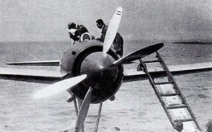
The 10000 form 10004th unit which derailed by an accident, and was completely demolished
(March, 1918 photography)
Outbreak day It is March 7 (1918) for 1,918 years
The outbreak time 4:57 (JST)
Place GunmaUsui-gunMatsuida-cho
Country Japanese flag Japan
Route Shinetsu Main Line
Operator The House of railroad
Kind of the accident Train derailment accident
Cause Ignorance (car trouble and estimate of the traction locomotive)
Statistics
The number of the damage trains 1 formation
Dead person Two people
Injured person Six (later two death)
I display a template

Shinetsu Main Line bear ノ flat station train derailment accident (しんえつほんせんくまのだいらえきれっしゃだっせんじこ) is the train derailment accident that occurred (1918) in the bear ノ flat House of railroad Shinetsu Main Line station (Matsuidamachi, Usui-gun, Gunma, current Annaka-shi) yard on March 7 in 1918.

A parked freight train went down the steep grade of 66.7 of the Usui Pass in the wrong direction on the main line by vehicle malfunction, and derailment was completely demolished after a plunge to the measuring line of the bear ノ flat station, and two people of trainman and the bear ノ flat station station employee died instantly, and it was the tragic incident that two severely injured crews suffered death, other crews four serious or slight injury in later.

Table of contents

Summary of the Usui Pass

Yokokawa - Karuizawa interval of Shinetsu Main Line was the mountains section where there was a section of most steep grade 66.7 ‰ to go over the Usui Pass and, not an adhesion type in the pike normal as incline measures (method depending on only the adhesive strength to occur between 車輪踏面 and a rail), opened it as a rack type pike using the Abt system rack rail (tooth rail). The exclusive vehicle with the gear which engaged with a rack rail was prepared for the locomotive which ran a rack rail section other than the wheel for the rail and the 10000 form electric locomotive introduced with section electrification completion of (1912) in 1912 went down it other than a rack type gear and equipped it with 抑速発電 brakes as run measures of the steep grade section.

Process of the accident

The outbound freight 191st train (one 10000 form double-header, freight train ten, existence lid train with brake vans, conversion 12.8) departed from the bear ノ flat station (1918) towards the Karuizawa area at 4:33 of the delay for 25 minutes from the appointed time on March 7 in 1918. The 10000 form did not include a double-header generalization control function [explanatory note 1], and, with the proper function locomotive (proper function machine) of bank engine (supporting plane) .2 eyes of the formation top, an engine driver and one assistant at organization boarded it two people per one locomotive. In addition, braking handling crew one person [explanatory note 3], other conductors two took a roofed train with brake vans (ピブ 1 form freight train [explanatory note 2]), and seven crews in total took a freight 191st train.

It departed from the bear ノ flat station, and the proper function machine engine driver felt a bad smell than the main motor equipped with to a locomotive (the 10000 form 10004th unit) soon in the neighborhood of Usui Pass 20th tunnel and admitted that the fume with the spark produced it with abnormal noise more in the 21st tunnel. The proper function machine engine driver corrected the notch of the master controller which I controlled the speed of from the power running tenth step to the eighth step and decreased electric flow quantity to drift to the main motor, but because the spark and the fume did not fit, I let I gave Mr. engine an order, and a locomotive-based rack gear tighten the obi brakes (band brakes) for the hand which acted and oneself turned off a notch and operated the vacuum brake which was common use brakes and tightened the hand brakes which acted to a wheel more. Therefore, the train urgently stopped it near the 21st tunnel west exit at 4:48.

Among the main motors carried two engines by a locomotive, I confirmed that trouble occurred to the coupling (gear coupling) of the motor for the rack gear drive as a result that a proper function machine engine driver checked a proper function machine. However, in addition to the abnormality not having been confirmed elsewhere, I took that train weight was relatively lightweight into consideration, and the proper function machine engine driver decided service continuation by the adhesion driving and asked Mr. assistance machine engine that visited the proper function machine for check for carrying out service by the adhesion driving, the transmission to an assistance machine engine driver.

After an assistant at supporting plane organization took a supporting plane (the 10000 form 10009th unit), the proper function machine engine driver promoted the departure towards an assistance machine aloud, but there was not any reaction, and the train started degradation (reverse run) from the assistance machine side suddenly just after that. Usually reach it than 32km/h equivalent to approximately 1.8 times of the driving maximum speed (18km/h) in time, and the degradation speed tightens the obi brakes for the hand and hand brakes in the proper function machine side soon; and for a train stop in duty, the assistance machine side of the obi brakes for the hand and hand brakes although operated a dynamic braking by the operation of the master controller other than tightening it, the rotor part of the main motor was damaged physically because speed at the time of the movement was unreasonable, and the brakes became unusable [explanatory note 4]. The same line car [explanatory note 5] which lost the slowdown means except hand brakes by the human power added to speed on a downslope of 66.7 ‰ more, and two freight trains of the formation intermediate part entered into the measuring line of the bear ノ flat station in the neighborhood of twelfth tunnel east exit at derailment, 4:57 and they exceeded No thoroughfare for vehicles and crashed into the rock face of the rear virtually. The freight train of the wooden body crushed it so as not to keep the original form, and two locomotives of all steel bodies derailed, and they were completely demolished.

Two people of one crew who boarded a roofed train with brake vans by this accident and one switch jockey of the bear ノ flat station which was on the side above the ground in total died instantly, and two people of assistance machine engine driver and the rear conductor in total suffered the death, four proper function machine engine driver others serious or slight injuries in total after a serious wound.

Accident cause

Because an assistance machine engine driver died, about the state just before the accident of the supporting plane which became the factor of train degradation, the details are unidentified. But, according to the testimony of the assistance machine stoker that lived again, it is said to not being the thing that backward movement was performed by the intention of the supporting plane engine driver that an assistance machine engine driver is apparent by having cast a master controller into the power running third step just before backward movement without taking at all means to usually have stolen on the occasion of the backward movement (degradation) driving in the incline section. An electric current did not flow through the brakes to the main motor by some kind of causes at the same time to operate a master controller for start although it remitted [explanatory note 6], and I let the notch of the master controller have 進段 more, but there was not the reaction and because backward movement speed increased, I used it together with various hand brakes and operated a dynamic braking, but the gear which linked the main motor did not turn as a result that not only the brakes became unusable, but also a damaged armature inhibited the turn of the main motor [explanatory note 4], and it was estimated that I destroyed a locomotive lateral tooth car and a gear and the both sides of the engaged rack rail and fell into a virtual no brakes state [explanatory note 5] by the inside damage of the main motor.

On the other hand, occur because there was the stop position of the train in a proper function machine engine driver and the train with brake vans crew on an ascent of 66.7 ‰ when remitted with brakes on the occasion of departure by the degradation of the train; judged it that was temporary, and it became clear to have remitted with brakes with the proper function machine, train with brake vans as preparations for progress. I brought no effect in the train which degraded at a violent speed over the steep grade of the thing which handled brakes again after having sensed abnormality and reached the collision. In addition, about the main motor trouble of the proper function machine that became the factor of urgently stopping it of the train, a part of the main motor lateral tooth car (pinion) case was damaged by abrasion, and it was concluded that it touched it and occurred to a gear without parts being fixed.

In addition, it becomes clear that was in a state that the work of the obi brakes for the hand remarkably decreased because the outskirts of the obi brakes for the twister were damaged for the oil leak from the main motor with the locomotive of supporting plane both sides a proper function machine.

Explanatory note

[Help]
  1. The ^ same shape type originally had a generalization double-header control function, and, in the beginning of completion, use was canceled later because malfunction occurred frequently although it inflected. It is written down in the original with "compound electric control method ニ support ラズ".
  2. The ^ ピブ 1 form freight trains were produced as a train with brake vans for the rack rail section newly from (1901) in 1901, and comprised the gear for the rack other than a normal wheel and were designed so that it was braked the part. As for the "pi" of form title "ピブ", the "bu" shows brakes car (train with brake vans) with a pinion (gear = pinion) each.
  3. It is written down with "a boiler maintenance man" in the ^ original.
  4. It is written down in the ^ a b original with "アーマチュア" "ノ "band wire" protagonist "motor" ノ turn ヲ inhibition シ to cut".
  5. Was crowded in comparison with an air brake using the compressed air which would be generally used later, and, in the mechanism, movement was remarkably slow with the remission, and the ^ a b vacuum brake was powerless for the brakes function on the occasion of the emergency. But a similar accident occurs in 1975 when automatic air brakes spread and had the perfect equipment toward a locomotive, and it is all overturn serious damage, a junk car, and four locomotives of the forwarding are dismantled on the site. The details refer to a forwarding locomotive derailment fall accident between railway accident _ (1950 through 1999) # Shinetsu Line Karuizawa - Yokokawa of Japan.
  6. It becomes clear that electricity was supplied normally during until 4:57 when an accident occurred from 4:48 when a train urgently stopped it according to the record of each transformer substation of Yokokawa, Maruyama, arrow ヶ 崎 established near ^, and, as for the reason that an electric current did not drift to to the main motor, it is unknown.

Original

Allied item

This article is taken from the Japanese Wikipedia Shinetsu Main Line bear ノ flat station train derailment accident

This article is distributed by cc-by-sa or GFDL license in accordance with the provisions of Wikipedia.

Wikipedia and Tranpedia does not guarantee the accuracy of this document. See our disclaimer for more information.

In addition, Tranpedia is simply not responsible for any show is only by translating the writings of foreign licenses that are compatible with CC-BY-SA license information.

2017년 1월 29일 일요일

Santa Maria grade frigate

Santa Maria grade frigate

Santa Maria grade frigate
Spanish Frigate Santa Maria (F 81) -01.jpg
F-81 "Santa Maria"

Warship grade general view
Warship class Frigate
Name of a warship
前級 Barea reply grade frigate
Next grade Alvaro デ バサン grade frigate
Performance specifications
Displacement A light load: 2,851Ton
A standard: 3,610 tons
Full loading: 4,017 tons
※It increases to 4,107 tons in F 85,86
Full length 137.7m
Overall width 14.3m
Draft 7.5m
Engine COGAG method
LM2500-30Gas turbine engine(20,500 hp Two engines
Emergency turning types raster (350 hp) Two engines
Screw propeller 1 axis
Speed 29.0Knot
Flying range 20 knots /4,200 nautical mile
Crew 223 people
兵装 76mm 単装速射砲 One engine
メロカ 20mmCIWS One engine
M2 12.7mm 単装機銃 Four engines
Mk.13 mod.4 missile 単装発射機
SM-1MR SAM
Harpoon SSM
を discharge is possible

One engine
Mk.32 mod.5 3 multi-launching short torpedo tube Two engines
Carrier-based plane SH-60B LAMPSHelicopter Two planes
C4I Navy tactics information system
(IPN-10+ link 11 / 14)
FCS Mk.92 (for the SAM, 76 millimeters gun)
Mk.116 (for the short torpedo)
Radar It is for AN/SPS-49(V)4/5 two dimensions anticraft search One engine
It is for AN/SPS-55 vs. water search One engine
It is for an RAN-12L/X CIWS target search, capture One engine
Sonar DE-1160 bottom of a ship equipment type One engine
AN/SQR-19(V)2 towing type One engine
Electronic warfare
Countermeasure
ネットゥーネル Mk.3000 electric wave detection interference device
Mk.137 ChaffFlareDischarge machine Two engines
AN/SLQ-25 vs. torpedo decoy One set

The Santa Maria grade frigate (Spanish: Fragata Clase Santa María) is warship grade of the frigate which the Spanish navy holds. The book grade produced the Oliver hazard Perry grade missile frigate whom U.S. Navy was equipped with under license in Spain.

Table of contents

Origin

In Spain, the domestic production of the battleship started a plan from the 1960s and, for the first group, constructed five Barea reply grade frigates from 1968 through 1976. This was designed based on Knox grade destroyer escort of U.S. Navy by American plaster cast and coxswain company, and I was constructed by military shipbuilding Co., Ltd. バサン government management public corporation of Spain [1].

However, in the United States, a plan of the Oliver hazard Perry grade who was the new frigate which I reviewed radically was pushed forward by a concept, and a name ship was started work of in those days in June, 1975. I received this, and a contract to license three ships based on a design of the Perry grade at once in Spain on June 29, 1977 equal to the next year when the last warship of the Barea reply grade was placed on duty, and to construct was concluded. But the license building plan of the Perry grade will be hardly delayed in those days until 1981 because a building plan of the light carrier "Principe デ ass toe ria" is realizing in the Spanish navy, and this was given priority to. A name ship was started work of on May 22, 1982, and building was started afterwards. 5.6 eyes were added in succession more in the fourth ship and 1989 at mid-1986. Six additional building was examined, too, but, with the abandonment of the NFR-90 (NATO Frigate Replacement for 1,990s) design, this was less realized [2].

Design

The designs such as the hull or the main engine become that all followed the Osafune figure of the American Oliver hazard Perry grade missile frigate, and it strongly lasts for an acute angle in front and behind a warship from a platform-shaped hull and bridge deck with the sloping clipper bow to a chimney, the helicopter hangar, and the characteristic such as the unified tall and stout upper part structure is approximately common. But the beam becomes wide, and it adds to the reconstruction nature with 46.9 feet (14.3m) for 45 feet (14m) of the model warship. It was thought that this secured deployment room for equipment for the future modernization [3]. In addition, two latter term building warships revised a township to cope with the boarding of the woman, and four building warships received similar repair later in the first half year [4].

The main engine was equipped with two General Electric LM2500-30 gas turbine engine by COGAG constitution equally and was done with a method to drive the pusher of 1 axis through a slowdown machine. In addition, LM2500 which book grade carries is a license production machine by Italian Fiat S.p.A. [4].

In addition, the power supply system is strengthened and is equipped with four Cato Allison 114-DOOL diesel generators of output 1,000kW with the book grade whereas the power output capacity of the model warship was 3,000kW and finds 4,000kW [4].

Equipment

It is an equipment side, but a thing of the Oliver hazard Perry grade who is a model warship is followed basically, but there is the part changed to a domestic production machine to a Europe machine about a proximity air defense system and the electronic warfare system.

C4ISR

Each radar followed a model warship, and AN/SPS-55 was carried for anti-water search use for anticraft search use AN/SPS-49. In addition, about the version of AN/SPS-49, I am assumed (V)5 by (V)4, latter term building warship two by four building warships in the first half year. In addition, the sonar carried DE-1160 for the export of AN/SQS-56 of the model warship in the bottom of a ship, too, and the AN/SQR-19(V)2 tactics towing sonar (TACTASS) was carried, too [4]. It was an export example world's first for a completion machine that this was placed as the most relevant antisubmarine sensor in Perry grade and was equipped in book grade [5].

In Perry grade, the simple model navy tactics information system (NTDS) was done with the equipment that was important to find ability-limited model Tata system and air defense ability that I put it together [6] and was equipped in the book grade. For the tactics information processing device, [7] that IPN-10 made in Italy was carried was changed by TRITAN-3 made domestic production with last two; is turned on [8]. Furthermore, the additional equipment for INISEL/FABA DORNA (Dirección de tiro Optrónica y Radárica NAval) and STING shooting conduct radar is examined to strengthen ability for weapon control. In addition, an SHF satellite communications machine to be connected to the communications satellite of the ヒスパサット company which is a Spanish satellite company than 1997 is equipped with later sequentially [4].

Weapon system

In Perry grade, the ability for air defense with the ability-limited model Tata system carried the important part of the concept as above, and this was equipped with in the book grade. It was equipped with Mk.92 by 砲射撃指揮装置 and a combined use with the Perry grade whereas it carried Mk.74 as a missile shooting conduct device by the conventional Tata warship. In the case of book grade, I am considered to be mod.6 by Mk.92 mod.2, latter term building warship two by four building warships in the first half year. For a discharge machine of the missile system catching the conduct by this, it carries Mk.13 mod.4 of 単装式 like Perry grade on the bow deck. I add it to accommodate 32 SM-1MR block V warship interceptor missiles for the air defense, and eight harpoon warship anti-ship missiles are usually equipped with for anti-water heat here [4].

The main battery is equipped with one 76mm コンパット gun made in Italian auto メラーラ company in 02 deck levels just before the chimney of the upper part structure central part like Perry grade. By SM-1MR and a combined use, I receive shooting conduct of Mk.92 as above. On the other hand, for CIWS, it carried domestic メロカ one at the rear end of upper part structure. This let RAN-12L/X low altitude caution radar, AN/VPS-2 shooting conduct radar link a gun turret with 120-caliber of long 20mm machine guns as 12 multi-launching, but replacement to RTN-30X is planned about the shooting conduct radar [4].

With the book grade, the ネットゥーネル Mk.3000 electric wave detection interference device which was a for two uses machine of electronic attack, the electronic warfare support by the design of Italy was equipped with whereas AN/SLQ-32 was carried by model warship for an electronic warfare system [4].

Warship of the same type

List of warships of the same type
# Name of a warship The start of work Placement on duty
F-81 Santa Maria
Santa Maria
May, 1982 October, 1986
F-82 Victoria
Victoria
August, 1983 November, 1987
F-83 Numancia
Numancia
January, 1986 November, 1989
F-84 Reina Sofia
Reina Sofia
October, 1987 October, 1990
F-85 ナバラ
Navarra
April, 1991 May, 1994
F-86 Canaries
Canarias
April, 1992 December, 1994

References

  1. ^ global security (April 15, 2013). "Baleares" (English). April 3, 2014 reading.
  2. ^ Bernard Prezelin (1990). The Naval Institute Guide to Combat Fleets of the World, 1990-1991. Naval Institute Press. pp. 473-474. ISBN 978-0870212505. 
  3. ^ Ikuya Kinoshita "O.H. Perry grade playing an active part abroad," it is 86-89 pages in "world vessels" 526th, Kaito Corporation, July, 1997.
  4. ^ a b c d e f g h Eric Wertheim (2013). The Naval Institute Guide to Combat Fleets of the World, 16th Edition. Naval Institute Press. p. 672. ISBN 978-1,591,149,545. 
  5. ^ www.forecastinternational.com (November, 2003). "SQR-19 TACTAS   (DOC) "(English). August 21, 2009 reading.
  6. ^ Yasuyuki Okuma "military affairs systems engineering" and bookshop, 2006. ISBN 4-906124-63-1
  7. The ^ Tomohiko Tada "combat system (combat system of the special feature modern warship) of the European warship," it is 88-93 pages, NAID 40018965308 in "world vessels" 748th, Kaito Corporation, October, 2011.
  8. ^ Norman Friedman (2006). The Naval Institute guide to world naval weapon systems. Naval Institute Press. p. 90. It is http://books.google.co.jp/books?id=4S3h8j_NEmkC. ISBN 9781557502629 

Outside link

This article is taken from the Japanese Wikipedia Santa Maria grade frigate

This article is distributed by cc-by-sa or GFDL license in accordance with the provisions of Wikipedia.

Wikipedia and Tranpedia does not guarantee the accuracy of this document. See our disclaimer for more information.

In addition, Tranpedia is simply not responsible for any show is only by translating the writings of foreign licenses that are compatible with CC-BY-SA license information.

2016년 11월 11일 금요일

Strong wind (plane)

Strong wind (plane)

Kawanishi N1K1 strong wind

Strong wind (latter term production type with the thrust type single exhaust pipe) of Sasebo flying corps

Strong wind (latter term production type with the thrust type single exhaust pipe) of Sasebo flying corps

The strong wind (きょうふう) is water fighter of the Japanese Navy which Kawanishi plane developed in the Pacific War. As for the mark, N1K1, the code name on the allied powers side were almost Rex. Shizuo Kikuhara that the chief design engineer dealt with two sets of flying boats.

This plane was designed as the body which assumed an air battle a main purpose while being a seaplane, but the number of the production does not reach 100 because I lose time of the activity because development ran into difficulties, and the performance is disappointing, and the operation was difficult. Two sets of water fighters which made Zero fighter a seaplane as a pinch-hitter until this plane appearance were developed, but this leaves a lot the number of the production for the military gains as such. Locality fighter (land plane) glaring eyes were developed based on this plane, and 紫電改 which was an improved development type played an active part for the ambush of B-29 and the U.S. carrier carrier-based plane which hit Japanese soil for Great War last years more.

Table of contents

Development process

I decided the development of the full-scale water fighter for the purpose of securing until airport completion when I invaded and attacked from the results that the Japanese Navy used 95 sets of water spy planes in substitution for an ambush machine and an air raider at the time of China incident and gave an effect to in the South Sea Islands of command of the air and the short compensation of the carrier plane in (1940) in 1940. It was not unusual that a seaplane played a key role before World War I and performed a battle duty, but the bodies for observation and the reconnaissance duty were often found in World War II, and the development of the seaplane which could perform a full-scale air battle was the one of a kind which reflected circumstances of Japan at the time [1].

In September, 1940, the navy ordered the trial manufacture of this plane to Kawanishi who had abundant development experience of the seaplane as 15 trial water fighters. The summaries of demand specifications shown in the trial manufacture remit are as follows.

  • Maximum speed: At an altitude of 5,000 meters more than 310 knots per an hour (574km/h)
  • A flying range (time): With cruising speed more than six hours
  • Armament: 20mm machine gun *2 and 7.7mm machine gun *2 or 13mm machine gun *2 and 7.7mm machine gun *2 or 7.7mm machine gun *4
  • 爆装: 30 kg of bomb *2

When I compare these specifications with the Zero fighter 11 type which was just put to practical use in those days, I exceed it more than 30 knots (56km/h) at a speed, and the same class is as above by two-thirds, armament at a flying range. Briefly, you should have said that it was demanded that I made a seaplane of the performance same as a new star main force fighter particularly the demand of the speed was approximately unrealizable for a thing demanded from a seaplane (even the maximum speed of model machine (J2M1) of the thunder and lightning that development was carried out for the same period is 578km/h). As a result, the maximum speed of the finished body was less than a demand nearly 100km/h, but I performed the technical effort that I mentioned later in the development team led by the Shizuo Kikuhara engineer of Kawanishi and wrestled for development eagerly in order to meet a demand. In addition, it is produced development by Nakajima airplane, and two sets of water fighters made from a Zero fighter 11 type by the filler-like implication will play an active part in the Pacific War beginning of the game because a stormy voyage was expected as for the development of this plane.

Design

Kawanishi took in various new keys like the auspicious purple clouds which were the water spy plane which produced it experimentally in the last year, and was ordered to meet naval demand specifications. I explain below the characteristic every each body part.

An engine and body shape
Mars (output about 1,500hp) made in Mitsubishi was adopted as an engine of the available large horsepower in those days. In Mars, a diameter (1,340mm) was relatively big for fighter use of the thing which was high power, and the nose part which located an engine was expected when air resistance grew big with the style of the normal single-engine fighter which became biggest. Therefore Kawanishi paid the attention to a fusiform body shape like the thunder and lightning that carried Mars in the same way. If it was the body with the same maximum product to cross-sectionalize by the wind tunnel experiment of the naval shipyard at the time, body center gathering was a point of the drag reduction, and there was a result to be advantageous, and the greatest position applied it to the fusiform body [2]. The engine was located nearer the body center to assume it spindle shape, and the cowl front was squeezed, and the propeller shaft was extended for clearance from the engine which I thereby produced to the cowl anterior extremity. This was a measure like the thunder and lightning, but the engine cooling fan to make up for the air mass flow from a narrow cowl opening equipped with by the plane was not equipped with.
The main wing
The middle wing placement that the main wing of the strong wind had little interference resistance with the body and spray of the water was hard to hit during a run was adopted. In addition, a laminar flow wing was adopted as the wing section. I delayed the detachment of the current of air on the wing with the laminar flow wing and it was the wing section which decreased air resistance and was expected when a speedup was effective. The thing of various shapes was studied, and the laminar flow wing was adopted to some warplanes (P-51 or brightly colored cloud), but the thing adopted for a strong wind was the LB type laminar flow wing which Ichiro Tani professor of Tokyo Imperial University (existing Tokyo University) invented in those days. The wing had a sectional maximum thickness position near 30% of the boom, but there was the maximum thickness position of the LB type laminar flow wing at approximately 40% of positions of the boom, and it was usually in the shape that current of air speed increased to wing posterior border (a wing of auspicious purple clouds is this LB type laminar flow wing). In addition, the smooth degree of the wing surface must be high, but there is the opinion that it might be difficult to realize precision necessary by the industrial arts at the time so that a laminar flow wing shows the effect.
Flap
Kawanishi developed the automatic air battle flap which operated an F ura flap at the most suitable angle according to speed and load automatically to do the battle with a land plane and the carrier-based plane in kineticism particularly turning characteristics profitably. This was Kawanishi's original invention to enable the self-regulation of the flap using a container (kind of Mano meter (liquid column manometor)) which I put mercury to detect dynamic pressure and load in. The strong wind relatively had a big loading to realize rapidity, but succeeded in acquiring turning ability not to fall behind two sets of small water fighters of the loading by this automatic air battle flap either. In addition, the device equipped with for a strong wind was a trial product, and a thing finished more was put on glaring eyes and 紫電改.
Float
Two sets of floats were comprised of the main float under the body and the supporting float under both main wings like water fighter. The main float was supported with the small V-shaped prop of the divergence in the front, and backward, thickness was supported with a wide prop thinly in the axis direction, and it was the shape that reduction of the air resistance was conscious of each (as for this, front and back are reverse to the placement of the prop of two sets of water fighters). The supporting float was considered for the gaining over-style plan like auspicious purple clouds at first, but it was said that it was rigid to receive the trouble in the plane, and to avoid complexity of the mechanism.
Propeller
 
Double inversion propeller of the model machine of the strong wind
For the inclination-related cancellation of the body by the spiral prop wash, I assumed the propeller of 2 feathers the set in two back and forth, and two folds of inversion propellers which reversed it each, and offset the torque by the race were adopted to a model machine of the strong wind. A detached room water landing became easy, and drivenness, the direction stability was good, and the reputation from a test pilot was very good, but the maintenance-related badness and oil leak to come were in this way changed to 3 normal feather propellers with the mass production type by the complexity of the propeller slowdown machine without dissolving. But a gap was left for the position where the second piece propeller should have been located with the production type in the first half year, and it was the characteristic appearance that a propeller spinner protruded from a cowl opening on the front.
In addition, as for the thing produced later, a meeting-type exhaust pipe was checked to a thrust type single exhaust pipe, and cowl anterior extremity was extended again, and the rear of the propeller spinner which there was of the redundant space was covered with a cowl by a trace of the contraprop.
In addition, the left torque of the "Mars" engine of liftoff output 1,460HP is strong and must handle a foot bar by considerable strength to deny it [3] and says that the detached room water landing was difficult [4].

Effect of the air battle flap

A navy aerodromics depot airplane part performs the experiment by the air battle flap from December, 1942 to February, 1943. The data recorded the process of the flight by a moving picture theodolite and they used a writing by oneself accelerometer together and were provided. Experiment altitude is 2,000m. As for the weight of the strong wind at the time of the experiment, 3,500 kg, loading are 148.9kg/ square m. Turning radiuses decreased to normal 70% - 80% when I used an air battle flap. The decrease of the turning time was not seen then. A diameter decreased about the somersault and decreased at time required for a somersault.

When a strong wind penetrated at 148 knots and circled, the load took 3.3G, and the turning radius needed 15.5 seconds at 180m, time. In contrast, as for the load, as for 4.1G, the radius, 140m, the time were 14.5 seconds when they penetrated at 151 knots and let a flap work at 19 degrees.

Turning radius
Use of flap (19 degrees) Approach speed Loading Turning radius Turning time
Unavailable 148 knots 3.3G 180m 15.5 seconds
Available 151 knots 4.1G 140m 14.5 seconds

Similarly, I did it and measured a somersault.

When I penetrated at 190.5 knots and did not use a flap, the somersault diameter was 305m, maximum load 3.4G. It takes 11 seconds by the top of the somersault, and, as for the speed, 105.4 knots, load 1.65G, the high difference are 437m (from the point that penetrated). In addition, as for the time required for the somersault end, as for the high difference, -111m (from the point that penetrated), the speed were 184.5 knots for 23 seconds.

In contrast, the somersault diameter became 250m, maximum load 4.0G when I penetrated at 189.4 knots and performed a flap at 19 degrees. As for high difference 398m (from the approach point), speed, 95.5 knots, the load are 2.0G by the top of the somersault for 9.5 seconds. In addition, as for the time required for the somersault end, as for the high difference, 95m (from the approach point), the speed were 142 knots for 17.5 seconds.

In use, a high difference occurred 200m in nonuse time, and the speed drop at the time of the use of air battle flap was considerably big again [5].

Somersault
Use of flap (19 degrees) Approach speed Somersault diameter Maximum load Top arrival time Top speed Top load Start→
Top altitude difference
End time Start→
End altitude difference
End speed
Unavailable 190.5 knots 305m 3.4G 11 seconds 105.4 knots 1.65G 437m 23 seconds -111m 184.5 knots
Available 189.4 knots 250m 4.0G 9.5 seconds 95.5 knots 2.0G 398m 17.5 seconds 95m 142 knots

Use, evaluation

As for the strong wind, it was adopted a regulation (1943) on December 21 in 1943, but the fight of the Solomon area was already settled by the victory of U.S. forces at the time and Japan advocated a desperate defense of the absolute national defense zone and went on the defensive, and a place of the activity of this plane developed for the purpose of invasion in the islands region hardly became extinct. It was such situation, but I am deployed and report B-24 of few things and patrol aircraft-shaped PB4Y and 撃墜破 of the B-29 to the seaplane corps that the strong wind presented it with regulation adoption in the Indonesian Ambonese island and Penang Island of the Malay Peninsula west coast offing. I seemed to often adopt the tactics to drop 30 kg of initiating-type bombs from the enemy plane upper part on the occasion of an anti-bomber battle in a period, and to give damage by the explosion. On the other hand, I was deployed in Sasebo flying corps and the Otsu flying corps (Lake Biwa) in Japanese soil and was included in an air defense duty, but there was hardly no war record [6]. I was used for 直掩 of the Operation others 1, Kikusui [7].

In addition, I enter into a battle in the form that 0 sets of one strong wind interfere F6F at war with the fighter in a warship off Tateyama, Chiba on February 16, 1945 and report one overthrowing after a fight war. That this is the only military gain that a strong wind gave for an enemy fighter [8].

That this plane loses appearance time after all, and two sets of water fighters which should have been originally the existence of the filler play an active part; have ended with a result. However, it may be said that the strong wind became the base of glaring eyes simply because there were such circumstances. 当時の海軍も強風が時局に見合わない存在であることを見抜いていたので発注数は予定より大幅に削減されたが、それは川西に事業の不振を懸念させ、本機を陸上機化した紫電の開発を促すことになった。 紫電とその改良発展型である紫電改は層流翼や自動空戦フラップといった本機の特徴を受け継ぎ、大戦末期に最後の奮戦を見せることになる。

強風の生産は川西のみが行い、総生産数は試作機を含めて97機であった。この内31機程が終戦時に残存していた。なお生産された全ての機体は強風一一型に分類されるが、紫電二一型を水上機としてフィードバックした強風二二型という派生型の開発計画があったとされている。

性能諸元(強風一一型)

  • 乗員:1名
  • 全長:10.58 m
  • 全幅:12.00 m
  • 全高:4.750 m
  • 翼面積:23.500 m²
  • 空虚重量:2,700 kg
  • 最大離陸重量:3,500 kg
  • エンジン:三菱 火星一三型空冷星型14シリンダー、離昇出力1,460hp)
  • プロペラ:住友ハミルトン 油圧式可変ピッチ定速回転3翅プロペラ
  • 最大速度:488.9 km/h
  • 巡航速度:352 km/h
  • 降着速度:131.5 km/h
  • 航続距離:4.8時間
  • 実用上昇限度:10,560 m
  • 上昇力:4,000 mまで4分11秒
  • 武装:九七式三型改二7.7mm機銃×2(装弾数各500発)、九九式二号三型20mm機銃×2(装弾数各60発)
  • 爆装: 30 kg of bomb *2

保存機

強風は戦後に性能テストのため4機がアメリカに輸送されたが、そのうちの3機はほぼ全部品が揃った状態でアメリカに現存している。2015年5月現在の状態は以下の通り。

脚注

  1. ^ 他国でも水上戦闘機の開発がなかったわけではないが、既存の陸上戦闘機(F4Fスピットファイアなど)を水上機化したものに過ぎず、しかも試作段階で開発が終了している。またイギリスブラックバーン社ではB-44という引き込み式フロートを備えた水上戦闘機の開発計画があったもののモックアップまでしか作られなかった(岡部ださく世界の駄っ作機(1)』 大日本絵画、1999年、ISBN 978-4499226899、160頁参照)。空港を建設するための重機や空母を多数保有していたアメリカ軍にとってはそのような機体は有用性が薄く、イギリス軍においてはそもそも多数の島嶼を侵攻・占拠するという戦争を経験していないからである。また当然ながら性能も陸上戦闘機や艦上戦闘機に比べて格段に劣った。なお第二次世界大戦後にアメリカ海軍は港湾地区防衛というコンセプトの基にコンベア社にF2Y/XF2Y/F-7というジェット水上戦闘機を試作させたが、これも量産されることはなかった。
  2. ^ ただしこの実験結果はプロペラ後流の影響を考慮しておらず、それを勘案すると胴体を後部にいくにつれて引き絞った二式単座戦闘機Fw190に代表されるスタイルの方が有利であるという見解もあった。
  3. ^ 渡辺 2002, p. 135.
  4. ^ 渡辺 2002, p. 136.
  5. ^ 海軍航空技術廠 『研究実験成績報告(空技報0358) 空戦フラップニ関スル研究(其ノ1)(15試水上戦闘機) (飛行機性能ノ研究第44回報告) 』
  6. ^ 渡辺 2002, pp. 136-140.
  7. ^ 渡辺 2002, p. 144.
  8. ^ 渡辺 2002, p. 142.

参考文献

  • 文林堂編集部 『世界の傑作機 No.124 強風、紫電、紫電改』 文林堂、2008年、ISBN 978-4893191588
  • 海軍航空技術廠 『研究実験成績報告(空技報0358) 空戦フラップニ関スル研究(其ノ1)(15試水上戦闘機) (飛行機性能ノ研究第44回報告) 』昭和18年。アジア歴史資料センター A03032133000
  • 渡辺, 洋二 (2002), "去りゆく水戦", 遙かなる俊翼, ISBN 4-16-724914-6  - 初出は『航空情報』1982年3月号

関連項目

This article is taken from the Japanese Wikipedia Strong wind (plane)

This article is distributed by cc-by-sa or GFDL license in accordance with the provisions of Wikipedia.

Wikipedia and Tranpedia does not guarantee the accuracy of this document. See our disclaimer for more information.

In addition, Tranpedia is simply not responsible for any show is only by translating the writings of foreign licenses that are compatible with CC-BY-SA license information.