| In this article, I explain 5 inch forward launch aircraft rockets.
For 3.5-inch forward launch aircraft rockets please see "".
Mk 4 For winglet folding type airborne rocket bullets, please read "".
— | —
Installed 5 inch FFAR
5 inch FFAR(5-inch Forward Firing Aircraft Rocket, a 5-inch forward launch aircraft rocket bullet) was developed in, and was launched from an aircraft and used for ground / anti-ship attack.
table of contents
History of development and operation
5 inches The predecessor of FFAR was developed by June. It has a non-explosion of 3.5 inches (about 8.9 cm) in diameter and was used to puncture and destroy the hull as an airborne ASW (fight) rocket bullet.
This rocket had sufficient hit accuracy for the ground / anti-ship mission, but warheads using explosive charge are essential for these missions, and because the diameter of the rocket bullet is small, the amount of enclosable explosive charge There was concern about the limited shortage of explosive power. Therefore Mk 35 A 5 inch bullet is attached to this rocket, FFAR was created. The actual deployment here is in December 1943. However, as the weight increased, the speed was only 780 km / h and the performance was not good. It was developed to correct this drawback.
List of aircraft operating 5-inch FFAR:
\ - Suddenly bomber on the ship
\ - ship fighter plane
Performance specifications
Type: Air-to-ground rocket bullet
Developed country:
Operating country: ·
Production period: 1943 - 1945
Weight: 80 pounds (36 kg)
Length: 5 feet 5 inches (1.65 m) in length
Diameter: warhead 5 inches (130 mm), rocket motor section 3.5 inch (89 mm)
Warhead: (High Explosive)
Warhead weight: 45 lb (20 kg)
Engine: 2,300 lbf (10.4 kN)
Range: 1 mile (1.6 km)
Flight speed: 485 miles per hour (781 km / h)
Induction device: None
Related item
\ - Air-to-ground rockets used in the UK during World War II
\ - The rocket for the anti-submarine which became the predecessor
\ - Improved air-to-ground rocket bullet
\ - rocket bullet with a diameter of 2.75 inches which was later also used for air-to-ground
\ - 5-inch air-to-ground rocket ammunition currently used in the US Navy etc.
footnote
1. ****Parsch 2004 2. ^ Parsch 2006
Source
Parsch, Andreas (2004). ".".. Directory. U.S. Military Rockets and Missiles. Designation-systems.net. Archives as of December 15, 2010. Browse January 24, 2011.
Parsch, Andreas (2006). ".".. Directory. U.S. Military Rockets and Missiles. Designation-systems.net. Archives from 15th December 2010. Browse January 24, 2011.
External link
There is a category related to****in Wikimedia Commons.
In addition, This site is simply not responsible for any show is only by translating the writings of foreign licenses that are compatible with CC-BY-SA license information.
Seven-passenger model released it from a model year in 2003 and was started, and five people got on, and a model was added in a model year in 2005. As for the former, the true gone (the Japanese name: Bighorn) latter is rodeo (the Japanese name: Wizard) and the succession of アクシオム. Ascender was still less sold in the country because I expressed the withdrawal from the Canadian market.
The ascender was not a voluntary development car of Isuzu and was OEM of GMC, エンボイ, and the production was carried out in OklahomaOklahoma City assembly plant (seven-passenger) of GM and Ohio モレーン factory (five-passenger). The seven-passenger model was abolished at a model limit with a lockout in 2006.
As for the engine, as for the latter, cylinder stop mechanism was acquired with two kinds of direct 6 4.2L and V8 5.3L in 2005.
With light truck business withdrawal in the United States of Isuzu, the production of the ascender was finished on June 6, 2008.
In addition, Tranpedia is simply not responsible for any show is only by translating the writings of foreign licenses that are compatible with CC-BY-SA license information.
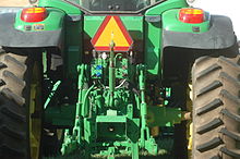
The PTO axis is placed in the central lower part sandwiched between the tires of right and left
The power take off (British: Power take-off) is mechanism to pick up engine power for the vehicle drive for the drive of the work machine. I am called power takeoff or merely PTO. There is a thing not to be proportional to that I am employed by a farm tractor, a tractor, a dump truck for the farming, the pump Carr such as the fire engine and am proportional to engine number of revolutions depending on a use. But I do not call the thing of the belt drive PTO like a compressor and an alternator for the air conditioning.
Table of contents
Risk
The PTO shaft which was covered to a protective cover made of yellow resin
The PTO shaft (universal joint) connected to PTO axis and it is a danger factor to be common to the agriculture beginning and the industry doing it. According to the American safe council (NSC), it was the cause that 6% affected PTO among the dead people with the tractor in the United States in 1997. When even the just small one flake of clothes contacts a reel, I am easily rolled up. It leads to the cutting of a hand and the foot or a fatal accident by clothes being rolled up.
On April 13, 2009, mark フィドリッチ of former major leaguer died by an accident by PTO during work at a home farm. When a friend discovered him, he works under a large dump truck, and a lawyer starts a statement saying "clothes were rolled up in the PTO shaft of the truck operating as for him.".
Some work machine comprises a protective cover made of resin to prevent that a worker is rolled up in PTO shaft, but there is a point to warn when I attach PTO shaft to a tractor and a truck. This is because it is illegal in some countries to use in a state without the protective cover of the shaft. The protective cover covers up the whole PTO shaft through a bearing or a sleeve and prevents the accident that I am fixed, and a worker is rolled up in PTO shaft by a chain.
History
The experimental power takeoff device had been already tried in 1878, but International Harvester Company (following, IHC) produced a tractor equipped with first PTO in 1918. An option set the equipment for PTO on a company's tractor from 15 to 30HP, and, in 1920, IHC became the tractor equipped with first PTO sent to the Nebraska tractor experiment station (Nebraska Tractor Test Laboratory).
The first PTO standard norm was adopted in April, 1927 by agriculture industry society (ASAE) in America. The number of revolutions of PTO was appointed as 536 ± 10rpm, and it was provided that the rotatory direction was clockwise (seeing from the tractor rear), and the number of revolutions was changed to 540rpm later.
In 1945, Cockshutt Farm Equipment company of Canadian OntarioBrandt Ford announced Cockshutt Model 30 equipped with live PTO. Live PTO was able to control a turn of PTO with the run of the tractor independently. As for this, there was the advantage that I ran at low speed and stopped, and there was even when driving a work machine by PTO. By modern tractor, live PTO is controlled by a push button switch and a changeover switch and raises safety by keeping away a worker from PTO shaft.
Technical standardization
In PTO of the bean tractor, dimensions and number of revolutions are standardized. The ISO standard of PTO was established in ISO 500 and was divided into ISO 500-1 (general specifications, safe requirements, dimensions of the protective cover), ISO 500-2 (dimensions of the protective cover by small tractor), three of ISO 500-3 (main PTO dimensions and dimensions of the spline, position relations of the PTO axis) by revision of 2004.
The basic PTO axis is used in 540rpm (rpm). The PTO axis used in 540 rounds has six splines, and the axial diameter is 1⅜ inch. In addition, there are two kinds of PTO axles to use in 1,000 rounds to drive an apparatus of the high load more. It is the PTO axis of the 1⅜ inch to have the big PTO axle of the diameter 1¾ inch having 20 splines and 21 splines. Judging from the tractor side, each these three kinds of PTO axes turns counterclockwise.
As for the early work machine such as Land Rover of 1948, there was the thing which adopted ten splines, but an adapter to convert into six general splines was provided.
In the agricultural machine maker, the index to express the horsepower of the tractor as custom displays the output to be able to take out of the PTO axis.
Equipment example
Tractor for a farm tractor, the farming
I turn a rotary by the power of the engine. However, the rotary is not necessary when I use a farm tractor as a chiller. Therefore the power transmission to the rotary is carried out through the axis called the PTO axis and becomes removable. In addition, there is a clutch to stop the operation of the work machine connected with in the PTO axis.
I put a transmission or a gear of the transfer in neutral (or a parking) and become the structure that I operate the PTO switch in the compartment or PTO lever, and power is transmitted to to PTO apparatus. The dump trucks are available for the some runs by the situation of the discharge spot, too, but when I do not use PTO, I compare it, and the power performance decreases.
Because an operation state does not depend on the driving condition when it is equipped with the small engine (subengine) for exclusive use of the freezing, the refrigeration device, the ability for cooling is high, but weight increases, and the greatest load capacity decreases, and there is the difficult point that the noise is big again. Therefore, security and lightweighting, the low noise of the load capacity may adopt PTO for the power of the compressor of the freezing, the refrigeration device for the purpose of becoming it.
Because concrete and water separate in a drum when the soft concrete stops stirring, and quality declines, PTO which can always turn during engine operation is used.
A pump motor scooter for the firefighting using the motor scooter of 250cc cubic centimeter displacement was produced experimentally for a strange vehicle with PTO and was adopted in 2004. It runs by itself in the spot and drives a pump after arrival by PTO.
In addition, Tranpedia is simply not responsible for any show is only by translating the writings of foreign licenses that are compatible with CC-BY-SA license information.
Generally it is connected electrically, and, with the normal semiconductor integrated circuit, signals are exchanged between each element elaborated on the top by the wiring by the pattern of the metal layer. In contrast, using the electric charge-like combination between the element next to each other, the element that signals are exchanged by the state of the electric charge being sent off in sequence is Charge-Coupled Device (CCD, charge coupled device).
I assume it image pick-up device in combination with a light receiving element, and there is the various application including the storage device of the sequential access equivalent to the delay line in the analog filter with a necessary comb filter in NTSC. There are the weak points such as smear phenomena while there is the advantage that there is at a light receiving area widely not to have area stolen by wiring for image pick-up device.
CCD image sensor and CMOS image sensor
Example of the image sensor device
Major solid image pick-up device includes CMOS image sensor other than CCD image sensor now. A lot of CCD image sensor had been used for a long time, but the spread of CMOS sensors advanced with the low-priced article and cell-phone, and a CMOS sensor exceeded it by the total shipment number in late 2004.
The production of the CCD is more difficult than a CMOS sensor, and the company to have of the production is limited for more complicated structure. In addition, it becomes the semiconductor which is considerably more expensive than a CMOS sensor (the details mention it later).
Purpose of the image sensor
I let the light receiving plane of the imaging element image the rays from a subject by the optical systems such as lenses, and the function of imaging elementelectrically converts the light and shade by the light of the image to the quantity of the electric charge and is to begin to read it sequentially, and to convert it into an electrical signal.
In the solid-state image sensing device, I electrically convert it with the row of the large number of light receiving element formed on one piece of silicon substrate. I produce an electric charge by light energy when I irradiate a light receiving element with light. It is main movement to transfer this electric charge by a CCD element outside. In addition, I may operate CCD itself for the transfer as a light receiving element when I use independent photodiode as a light receiving element (later description).
A principle and structure
I control the voltage and transfer an electric charge
As for the CCD, the structure that approaches it, and displayed MOS capacitors is basic. The CCD established a large number of electrodes on the oxidation film of the silicon substrate surface with kind of the MOS structure semiconductor element and created potential well (English version) (well of the electric potential) by giving each electrode of the MOS structure the neighboring, different voltage and allowed maintenance to transfer an electric charge in semiconductors using this.
The electric charge of each element is transferred to the next element all at once by controlling the voltage in addition to each electrode appropriately. A bucket brigade type can in this way pick up the electric charge that each element maintains outside sequentially. It is the operation of the digital circuit same as parallel = serial number shift register and is just said to be the shift register who can treat analog quantity. If I give you a delay equivalent to the transfer number of times for the number of elements and take the electric charge that I input using this property from one line of edge out of the contralateral edge, I can operate it as delay line (derailleur in).
One-dimensional image sensor
I say the linear image sensor and arrange photodiode to one line and locate CCD in this in parallel. I transfer the electric charge that photodiode electrically converted by one exposure to a CCD element corresponding to each pixel all at once and I give CCD a transfer pulse successively and begin to read an electric charge sequentially. The next exposure is enabled when I finish outputting the electric charge of all pixels.
Because the one-dimensional image sensor can electrically convert only a linear image, I relatively move a subject and image sensor or cover the whole subject by relatively moving the same class by an optical system. It is a method used with a facsimile and a copier, image scanner. Movement time is second order and slow one, and the subject is almost limited to a still image.
Two-dimensional image sensor
I said the area image sensor and spread it all into a plane form by grillwork or other placement. There is some structure by the sequence of CCD and the light receiving element.
Inter-line type
Structure of the inter-line type Charge Coupled Device imager
Inter-line type CCD image sensor is used many with a general video camera and digital camera in two-dimensional image sensor. I locate the photodiode of the light receiving department and the perpendicular transfer CCD of the electric charge transfer department every one line in turn and am the structure that connects the edge of the perpendicular CCD line to each element of the stability transfer CCD, and, as a whole, located it in the pectinated form. The CCD for each transfer is covered with a shading film not to electrically convert it. In addition, a transfer gate acting on each element of the perpendicular CCD corresponding to photodiode and the pixel of each pixel as an analog switch between is put. I do the reading for one as follows and perform it.
I close a transfer gate.
I am exposed to light in photodiode and accumulate an electric charge.
I open the transfer gate and transfer an electric charge to each perpendicular transfer CCD from photodiode all at once.
I close a transfer gate.
I transfer an electric charge of each perpendicular transfer CCD for once and transfer the electric charge of the pixel equal to the edge of each line to horizontal transfer CCD.
I give horizontal transfer CCD a transfer pulse sequentially and output all horizontal pixels.
It is repeated until I return to 5 and retrieve all pixels of the perpendicular transfer CCD.
The pixel of all all areas would be in this way scanned sequentially.
Because it is necessary to perform 30-60 times per second of exposure, transfer, reading to use it for a video camera, as for the electric charge transfer from photodiode to perpendicular CCD, it is performed again during each stability return wire period during a verticality return wire period beginning to read it from stability transfer CCD.
Other model
Structure of the full-frame transfer type Charge Coupled Device imager
Structure of the frame transfer type Charge Coupled Device imager
I have full-frame transfer type structure, CCD for the light receiving and CCD for the transfer electrically converting with each element of the perpendicular transfer CCD directly elsewhere, and there is the frame transfer type CCD transferring to CCD for the transfer from CCD for the light receiving during a verticality return wire period. The ratio (opening rate) of the element area that the light is because CCD for the transfer is unnecessary as for the full-frame type is big and is more sensitive than an inter-line type. On the other hand, the animation photography is difficult because a mechanical shutter becomes required not to receive light during electric charge transfer. The frame transfer type is similar to a full-frame type at the high point of the opening rate, but an element area grows big as much as I have CCD for the transfer particularly.
Because there is a reading circuit in the other side of the light receiving department, the backside-illumination type CCD can do a light receiving area widely and is more sensitive than the tip of the area. However, thermal capacity largely decreases by sharpening a silicon substrate layer for backside-illumination, and dropping it, and the fever by the dark current increases. Some kind of cooling means is necessary to suppress the influence of the heat noise by this; of the small size price reduction of the photography apparatus is a big hindrance.
After invention in Bell Laboratories, an applied study as as delay line or the image sensor advanced, and the color television camera which was practical in the 1980s was manufactured, and a trial manufacture camera replaced it in an image pickup tube by progress of the semiconductor processing technique in the late 1970s. A digital still camera is born in the 1990s and is substituting with a silversalt camera in the early 21st century.
The CCD image sensor is made from a silicon wafer like other semiconductor integrated circuits. I do not change with the production of other semiconductor integrated circuits basically, but the consideration to a light receiving side is demanded, and the normal moulding is maintained by the implementation to a substrate without being performed.
Applied
Digital camera
Video camera
Cell-phone with camera
Copier, facsimile
Gastrocamera (upper part gastrointestinal tract endoscope)
Color imaging with the CCD image sensor
Pixel placement of the LCD indicating element
Buyer sequence of the single plate-type color camera
Space placement of the CCD element of 3 boards type color camera
Version (green resolution priority) of 3 boards type
Like many other color photography methods, there is a multi-disc (3 boards) method to photograph a single plate method to elaborate each color of RGB to one piece of sensor and the thing which separated each color of RGB optically with each sensor.
Single plate method
CCD image sensor itself does not have the discriminability of the color like other image pickup tubes and solid-state image sensing devices. The sensitivity properties every wavelength of the general CCD (spectrum properties) have peak properties of the slow chevron at about 300nm - 800nm and cover a visible light range. Therefore, it is necessary to perform a color separation in the three primary colors of the light by a color filter to perform color photography [11]. The three primary colors resolution includes a thing by a method and the subtractive color process by the additive color process, and the simple additive color process of postprocessing be theoretically superior to color reproduction characteristics, and it is said that the subtractive color process that there is much light passage quantity is superior in sensitivity, but the difference is not remarkable by the comparison at the product level because there are the performance of the element level and the difference by the later color processing technology.
Some methods are thought about in the mask pattern of the color filter. At first, like indicating element such as the LCD, a method to place a light receiving department of each RGB for each pixel spread all over the square is thought about. A model and the consistency with the value of the color are good every each pixel such as the image data, but each light receiving department becomes slim and must elaborate microstructure with again triple pace and is not all right in production.
Generally, it does aspect ratio with 1, or it is desirable for each light receiving region that it is near because it puts microlens with the solid-state image sensing device every light receiving department. Therefore, the technique that I spread a square all and use a filter of the buyer [12] sequence (Bayer arrangement) is common.
With the buyer sequence, as for the green resolution, N/2, the red and blue resolution create groups of RGB of the N unit for total pixels N of the CCD to become N/4 by operating interpolation using the output of neighboring pixels every each pixel. Because a picture is affected by a method of the interpolation operation, each camera maker devises a processing method originally. The spectral sensitivity of human eyes assumes green neighborhood a peak, and the reason why I make a green pixel 2 times here is that green resolution improves apparent resolution.
I may adopt 3 board methods to meet demand performance of high resolution, the high sensitivity with the color television cameras for the broadcast. This prepares for one piece of CCD image sensor in each RGB color each with the thing like the method of the image pickup tube era that the method with the filter of the microstructure such as the statement above was impossible and I let you divide it into each color by ダイクロイックプリズム and expose to light and take a color signal of RGB each. In 3 boards type, I may adopt technique to improve the apparent horizontal resolution because 1/2 pixel moves an element for two pieces of green horizontally as well as RGB equality method. In this case two colors of CCD for blue, the red goes down for common use, and the resolution decreases, but aims at what I can compensate it for by improvement of the green resolution. Furthermore, the color imaging of two pieces of CCD methods is possible when I make green CCD only one piece (2 board methods).
Other
It is not a practical thing, but there is technique to let you perceive a color using an optical illusion phenomenon. I refer to a top of the Ben ham.
I reduced a noise due to heat by cooling off and enabled long-time exposure. In addition, there is the direction that confuses shot noise with a thermal noise, but is a noise of the another kind really.
Size name of the CCD image sensor
There are two ways of methods about the size name of the image sensor. This is similar about the CMOS image sensor.
By the inch unit call; size
It is size to be called by the inch unit including 3/2 inch, 1/1.8 inch, the 1/2 inch. このサイズはイメージセンサの撮像面の実寸を示すものではなく、呼び名に相当する管径の撮像管の撮像面サイズと等しいことを表す。 2/3インチセンサの場合は(16.9mmではなく)2/3インチ撮像管に相当する対角11mm(8.8mm x 6.6mm)、1/1.8インチセンサでは対角8.93mm(7.18mm x 5.32mm)、1/2インチセンサでは対角8mm(6.4mm x 4.8mm)が実寸となる。 これはCCDイメージセンサの初期の用途がテレビカメラ用の撮像管を置き換えるものであったため、レンズなどの光学系を設計したり選択したりする際の便宜を考慮してこのような習慣が生まれたものである。 同様な理由により、特に断らない限り画面の縦横比は標準テレビ画面と等しい4:3が主流である。
In addition, Tranpedia is simply not responsible for any show is only by translating the writings of foreign licenses that are compatible with CC-BY-SA license information.
A thing that structure in itself is very simple, and an iron ball rolls on the course consisting of two rails. The iron ball which arrived at the terminal of the course continues moving by potential energy by the height after movement by an elevator again to the terminal to the initial point.
I can make a great variety of one's own courses as far as it is a product enjoying a run after the completion from the making of the course, and resources and the idea of the creator permit it. Gimmick parts such as "seesaw" "moonsault" "start unit" "divergence" are attached depending on the series.
History
It is released in 1983 and sells approximately 1 million (series total) during four years. It went out of print, but consumers request type shopping site received a request of the rerelease in "I beg you", and the new series was released afterwards in 2005.
Component
Iron ball
The iron ball which rolls on a course. I use the carbon steel ball of the 1/2 inch.
Support shaft
I am used for the fixation of the course and the constitution of the elevator. I use an aluminum shaft of 5mm in diameter.
Rail
The nylon tube of the 1/8 inch to be used to make a course.
Rail support
Parts to prevent fixing the distance of two rails, and an iron ball from falling.
Arm parts
The rail support that I can fix to the support shaft. I can prevent the bend of the course by the heaviness of the iron ball.
Gimmick parts
The gimmick parts are installed in the middle of a course, and they are parts / unit group giving a change for the run of the iron ball. There is the thing which does not say that it is attached by the series.
Seesaw
I am constructed by the rail which I cut into short pieces and the seesaw parts which a weight is fitted with in the rear, and a connection part with the shaft becomes the fulcrum. When there is an iron ball, I send a degree of leaning, the iron ball which I got on to the lower course and come back to the again original degree of leaning when an iron ball disappears.
Moonsault
I am comprised by central rotary unit and ball tray, shaft two different in the length and weight. I carry an iron ball to the lower course when I receive an iron ball in a ball tray while length turns.
Divergence
I am constructed by course divergence parts. It is the part which divides one course into two and changes the line of the passing iron ball in turn.
I am constructed by the central main shaft through three lateral shafts and spiral parts, a motor box. The side turns a main shaft by a motor and carries an iron ball contained between a shaft more lateral than a course terminal to the course initial point of the elevator upper part.
Representative course layout
Loop
The iron ball which ran from the upper course passes the vertical course that I turned. Drops more than the twice the loop diameter are necessary to prevent an iron ball from stalling on the way.
List of products
Old series
SPACEWARP SET 10
SPACEWARP SET 15
SPACEWARP SET 20
SPACEWARP SET 30
SPACEWARP SET I
SPACEWARP SET II
SPACEWARP SET L
SPACEWARP SET W
SPACEWARP ACTION 1
SPACEWARP ACTION 2
SPACEWARP BLUE WINGS
SPACEWARP SPACE TREE
New series
SPACEWARP 3500
SPACEWARP 5000
SPACEWARP 5000 Limited Black
SPACEWARP 10000
SPACEWARP Start
SPACEWARP desktop
SPACEWARP X family game
Similar product
The product which Canadian Mega Brands company having a position of the second place released in the United States in the toy industry of the iCoaster world in 2007. I move the metal ball on the three-dimensional track which a person of game assembled freely by potential energy and magnetic force. The three-dimensional track a sound let beam, and link an MP3 player, and can do it. Toys"R"Us Japan started sale in Japan on August 27, 2008.
In addition, Tranpedia is simply not responsible for any show is only by translating the writings of foreign licenses that are compatible with CC-BY-SA license information.